Prepare the car:
Before fitting the System Panel in the car,
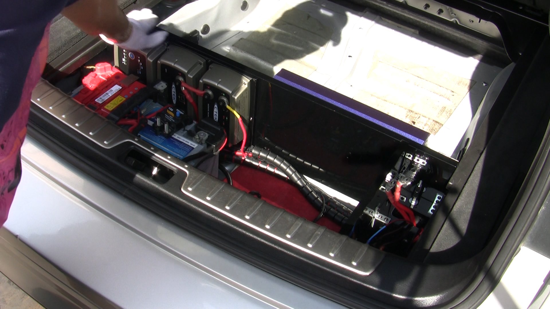
- The Luggage Compartment Pan (A) (part no. 51476981061) and the Battery Cover (B) (part no. 51476981050) will have to be removed to make room for the installation.
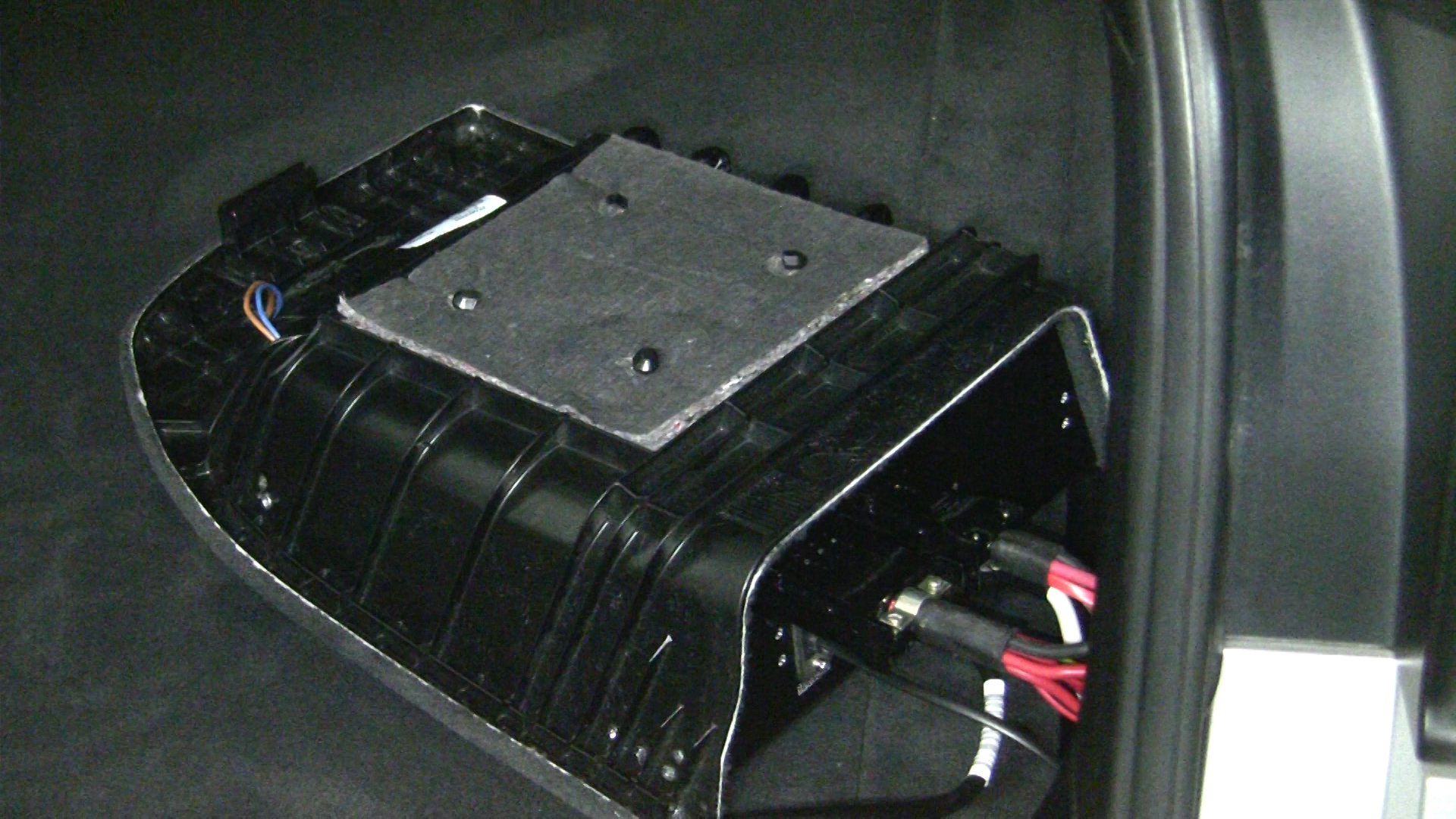
- The X6 Interior-Rear-Storage Compartment Right (C) (part no. 51476981048) sits right underneath the Right Flap (D). An 8cm hole will need to be opened on the front side of this Storage Compartment, large enough for the connecting Powerpole plugs to pass through it.
Prepare the PM panel:
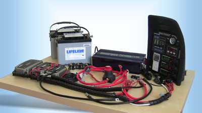
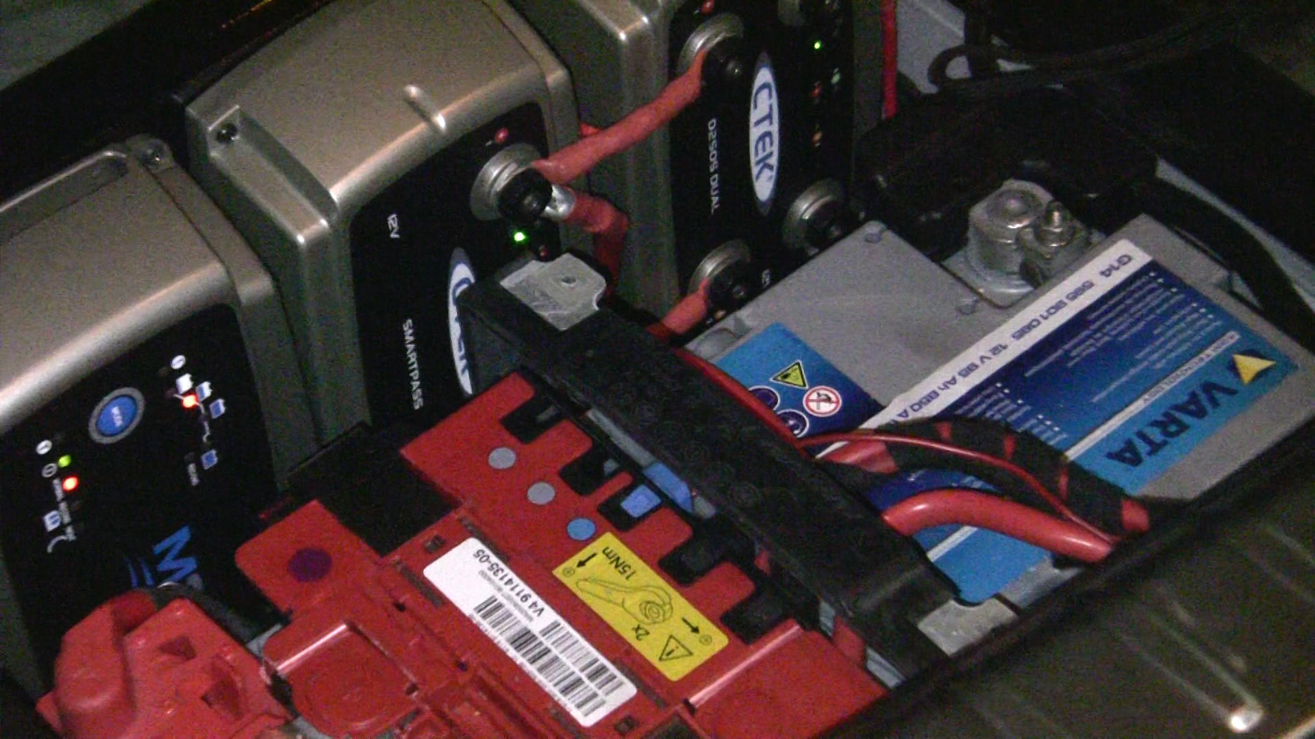
- Attach all the PM components (D250S, Smartpass, M300 and Grounding Bus Bar).
- Now connect all cables to each PM component (LOOM1 & LOOM2).
Prepare the SP by making sure:
- All 3 base brackets are attached and
- Both side brackets are not attached so as not to interfere with the installation (we will add them later on).
- The 2 bottom Inverter screws are screwed onto the SP to allow easy Inverter fastening.
- Attach the PM panel to the SP and take the SP to the car for installation.
CAUTION: Please arrange for adequate protection of your rear bumper during installation to protect it from scratches.
Installation comprises of 10 sections. Follow the instructions closely for each section in sequence.
- System Panel (SP)
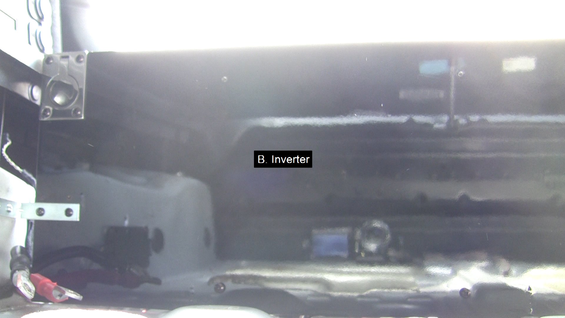
- Inverter
- Cable Harness
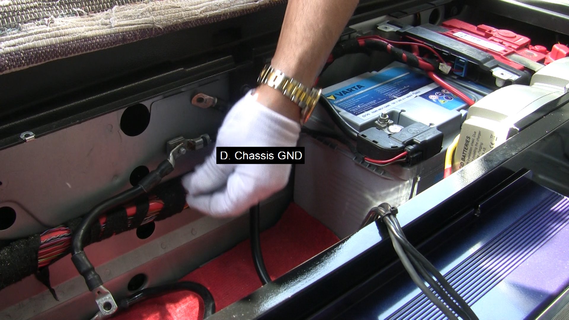
- Chassis GND
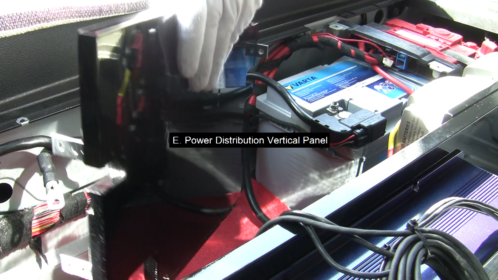
- Power Distribution Vertical Panel
- Power Distribution Bottom Panel
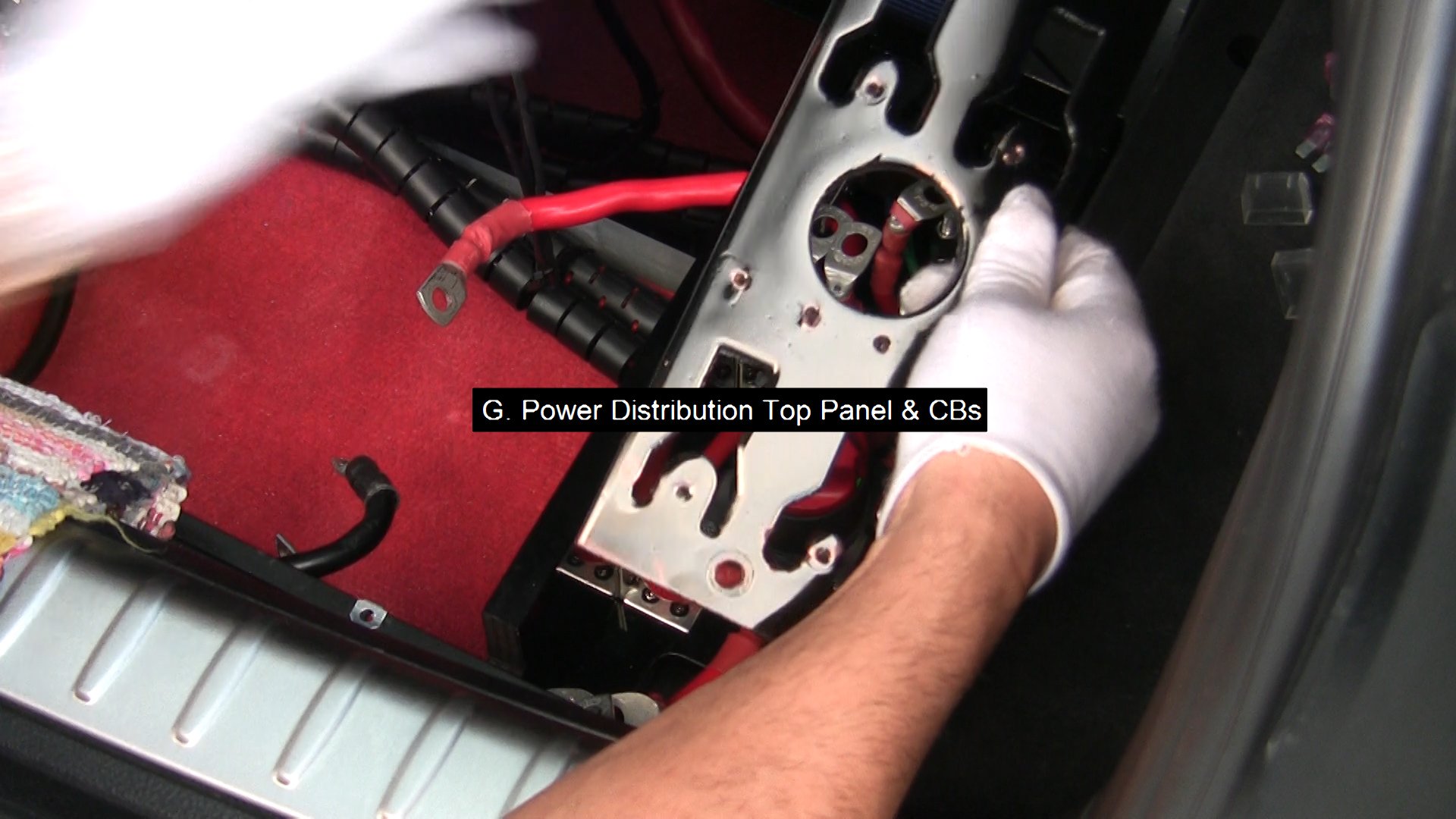
- Power Distribution Top Panel & CBs
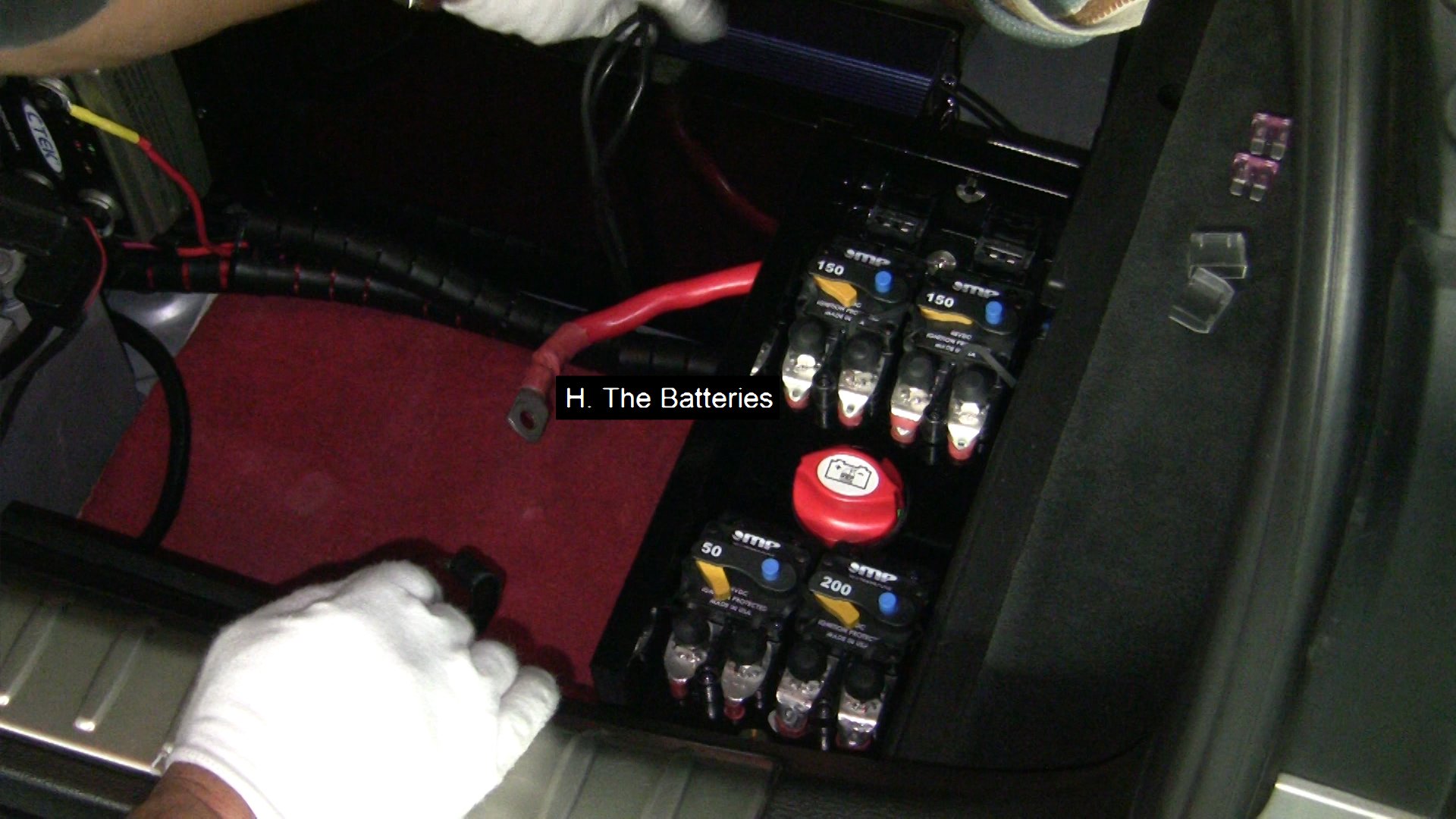
- The Batteries
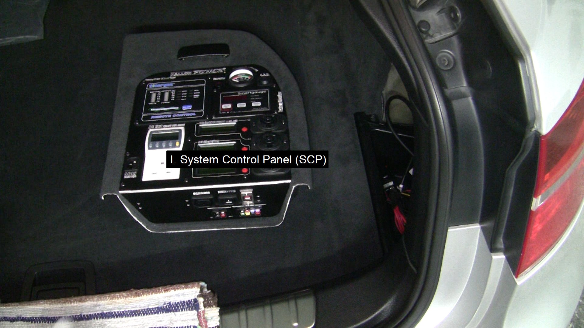
- System Control Panel (SCP)
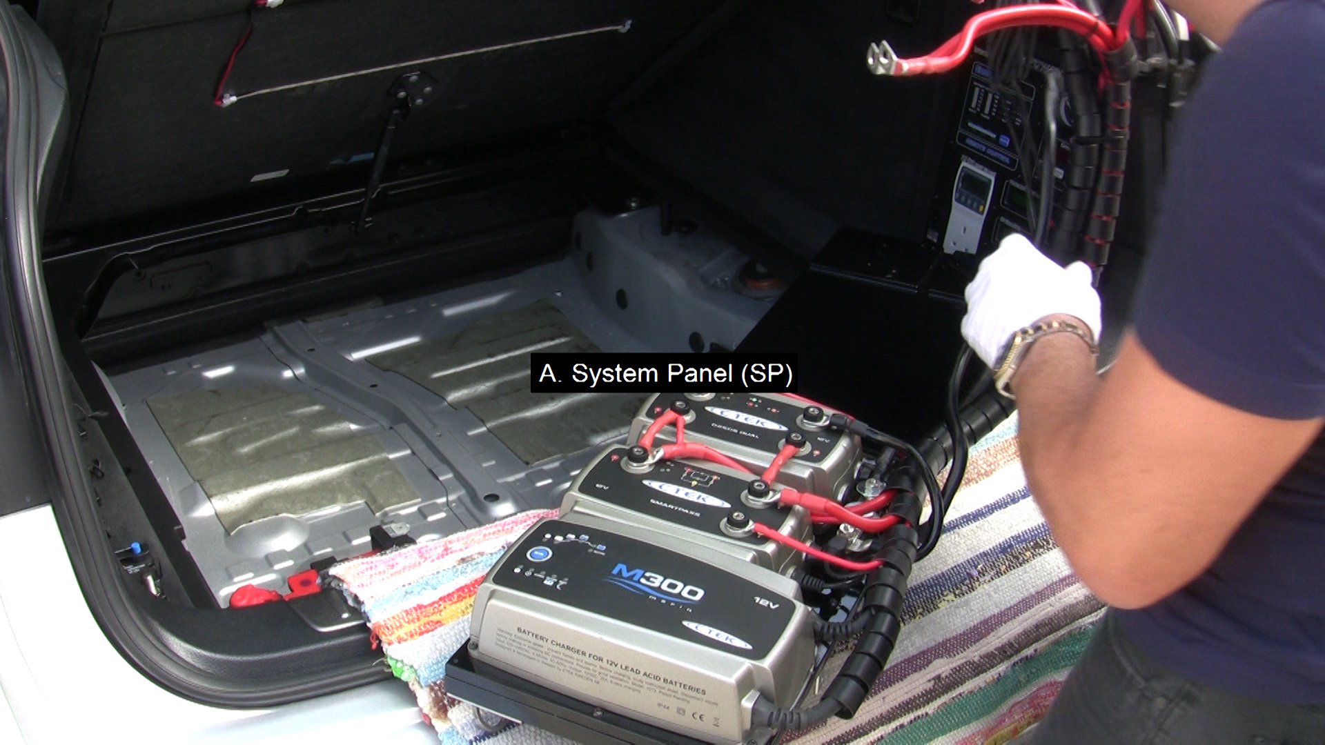
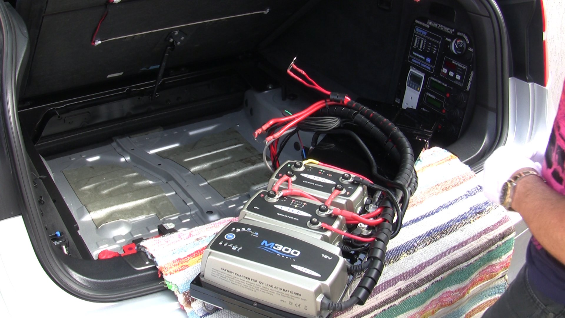
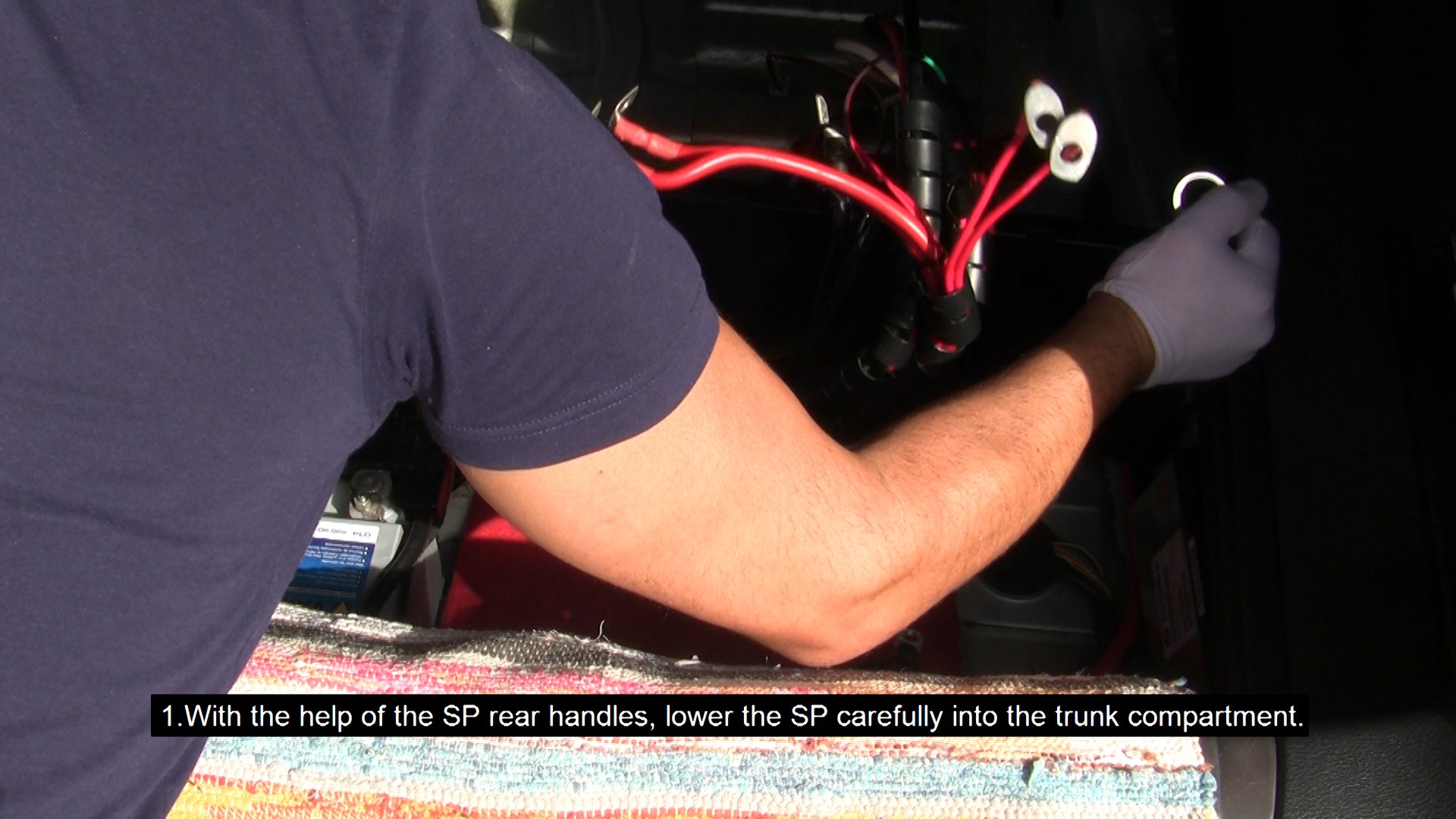
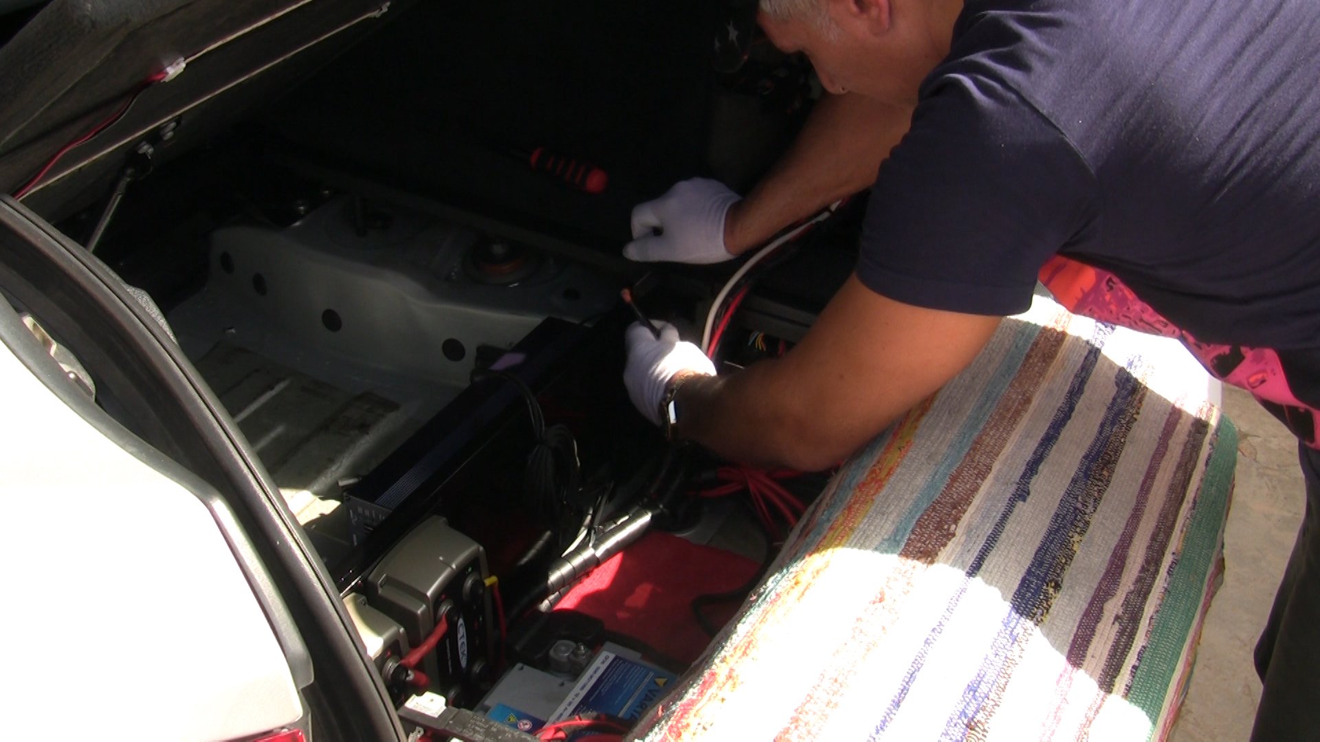
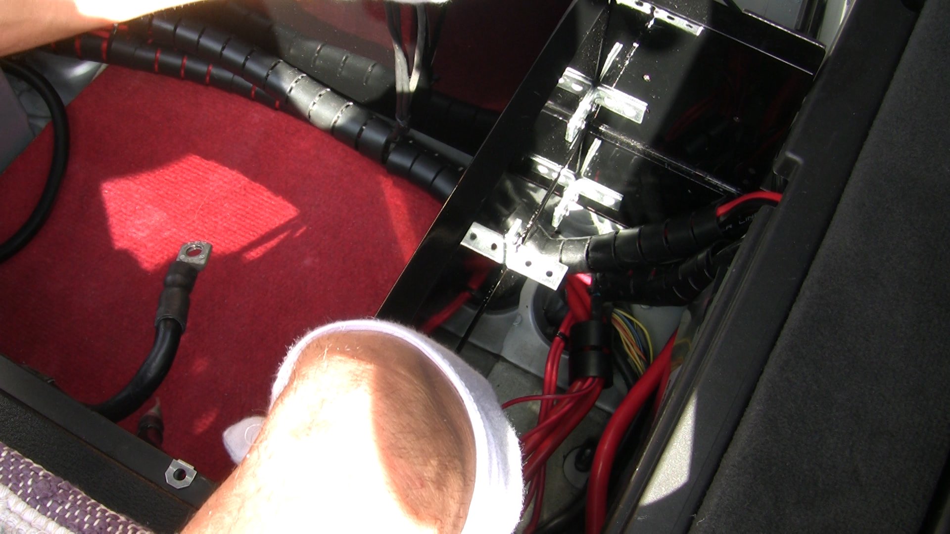
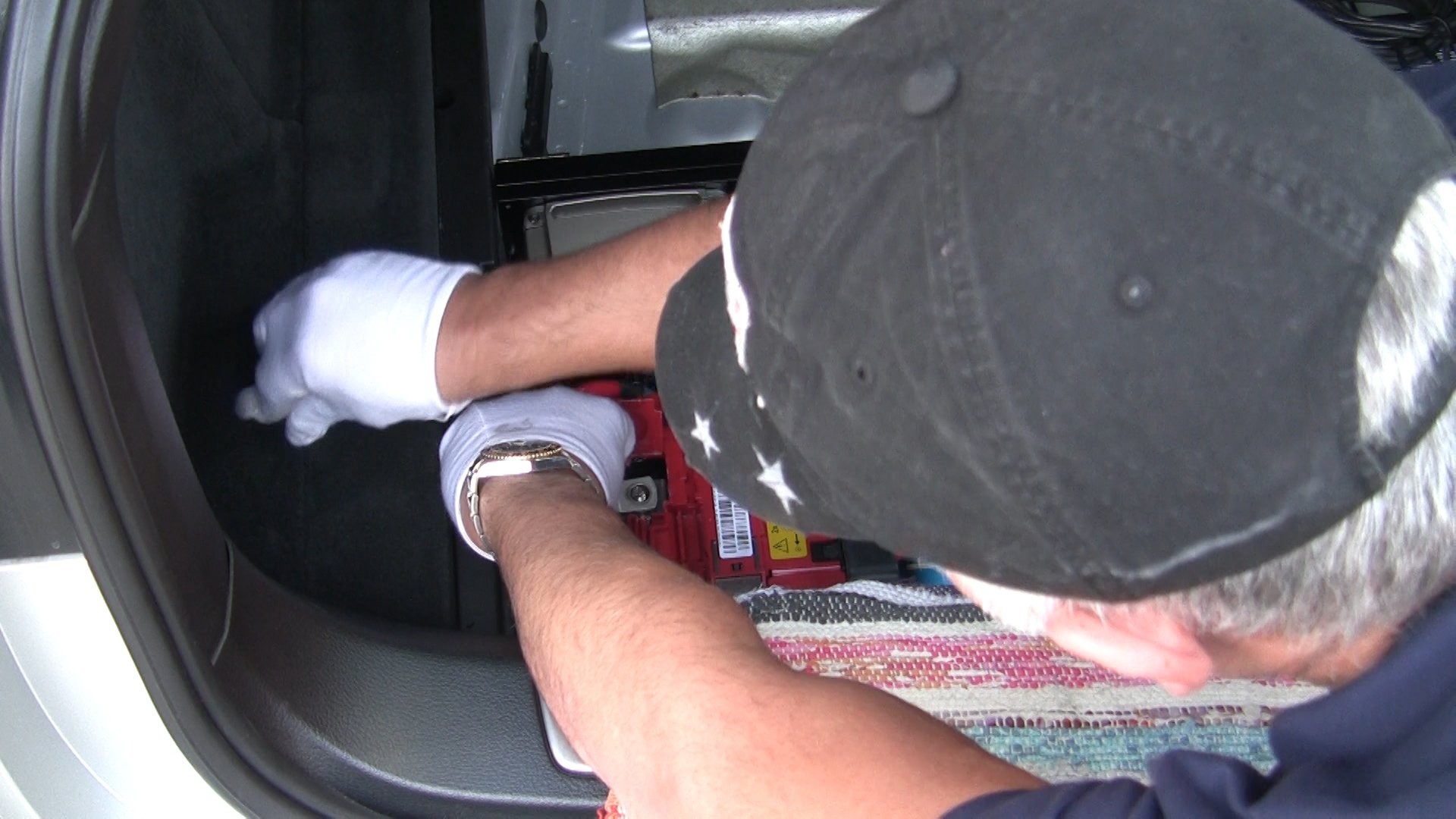
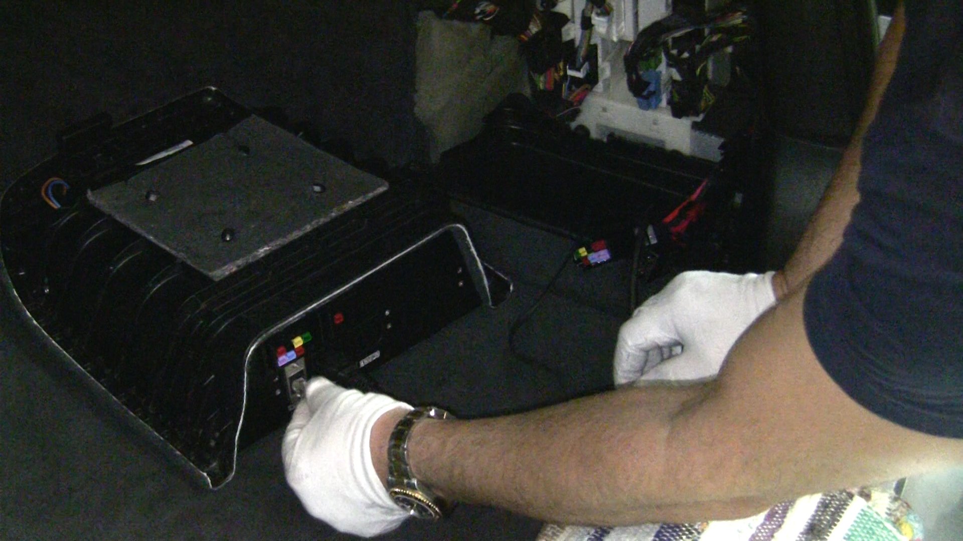
- With the help of the SP rear handles, lower the SP carefully into the trunk compartment.
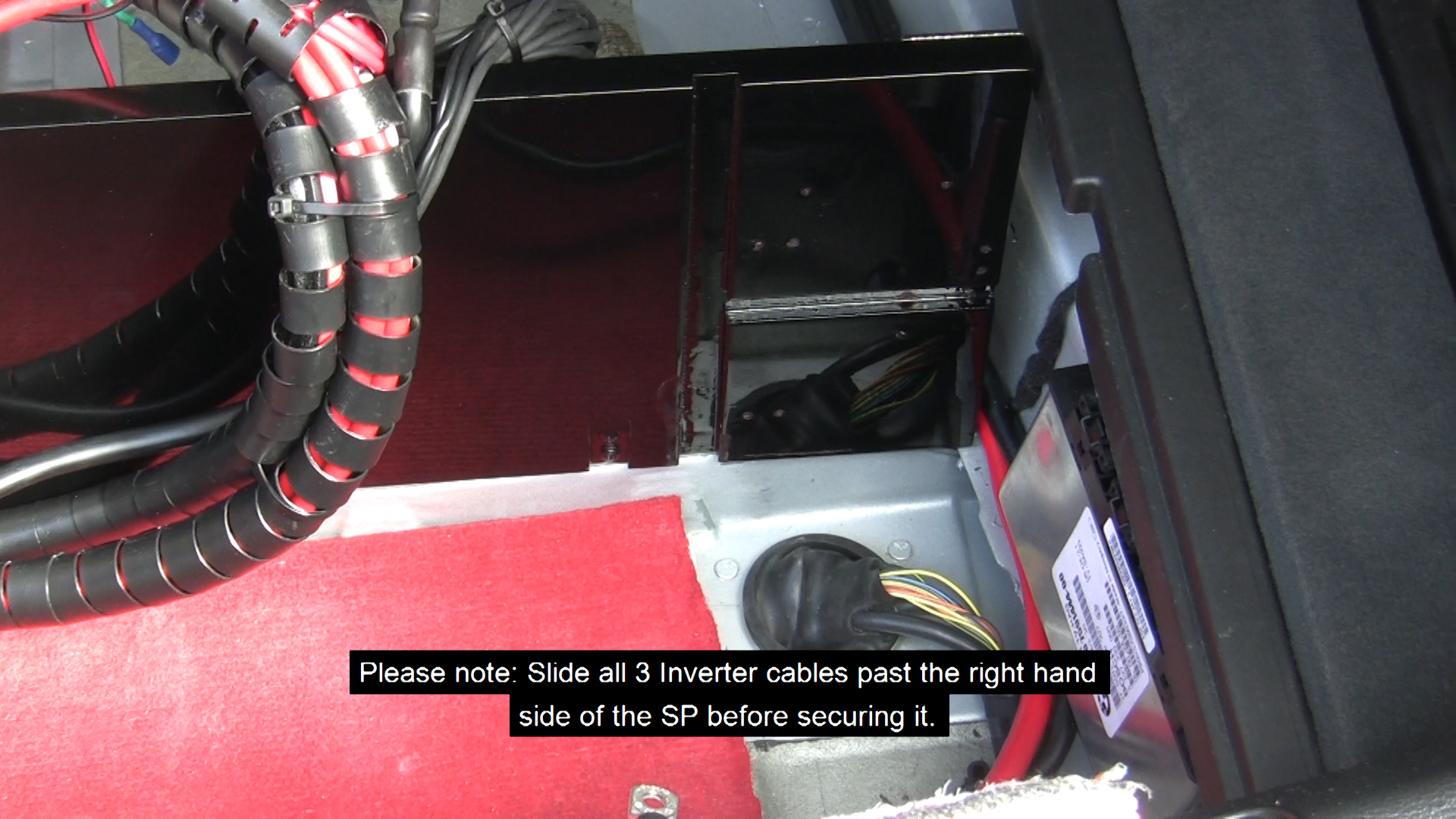
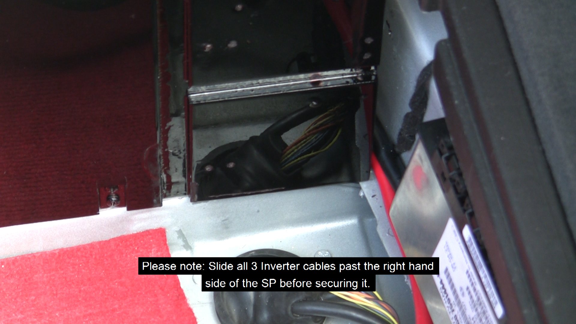
Please note: Slide all 3 Inverter cables (Green color coded - INV/P-CB7, INV/N-SBB/N, INV/GND-BB) past the right hand side of the SP before securing it.
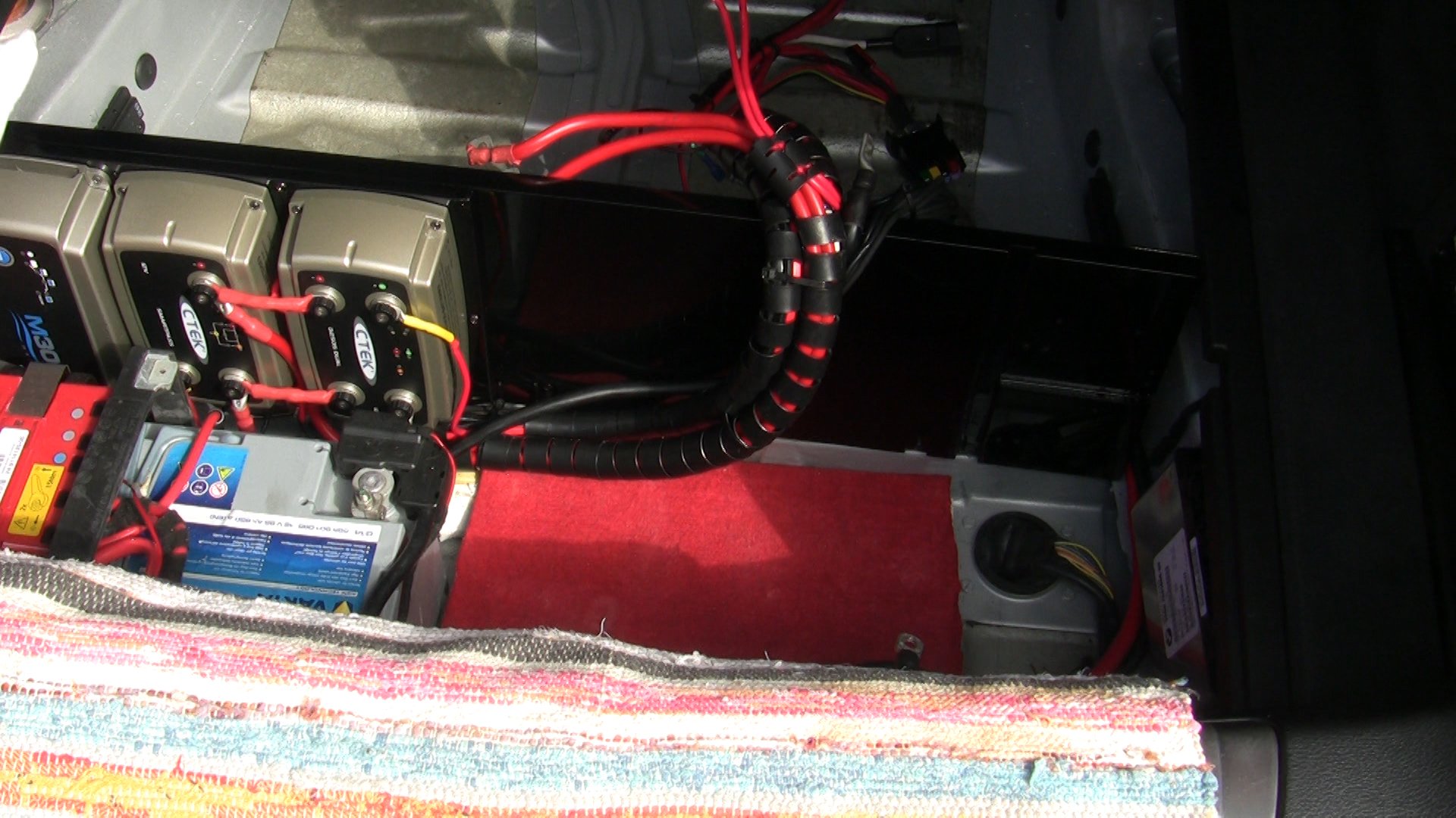
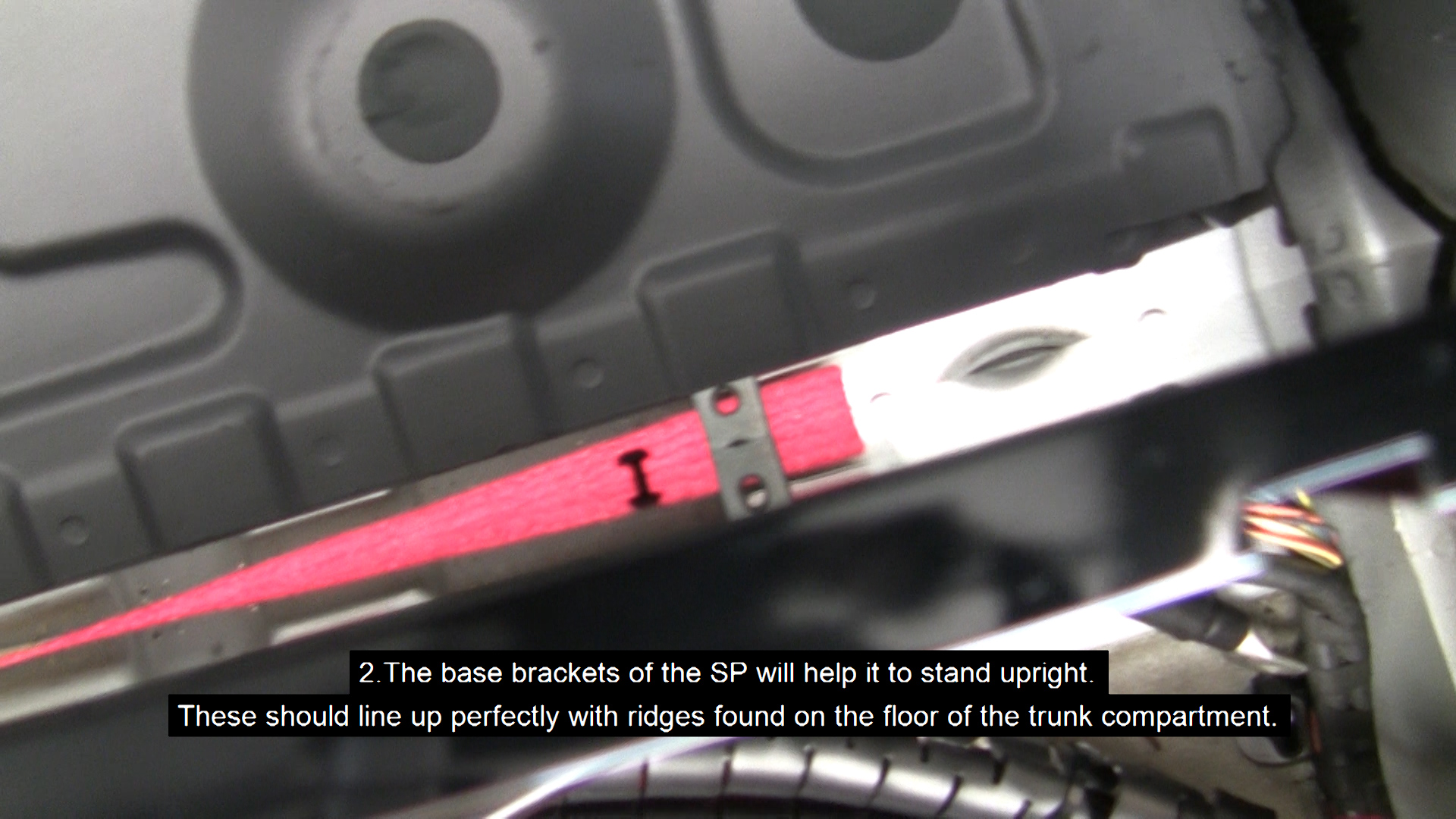
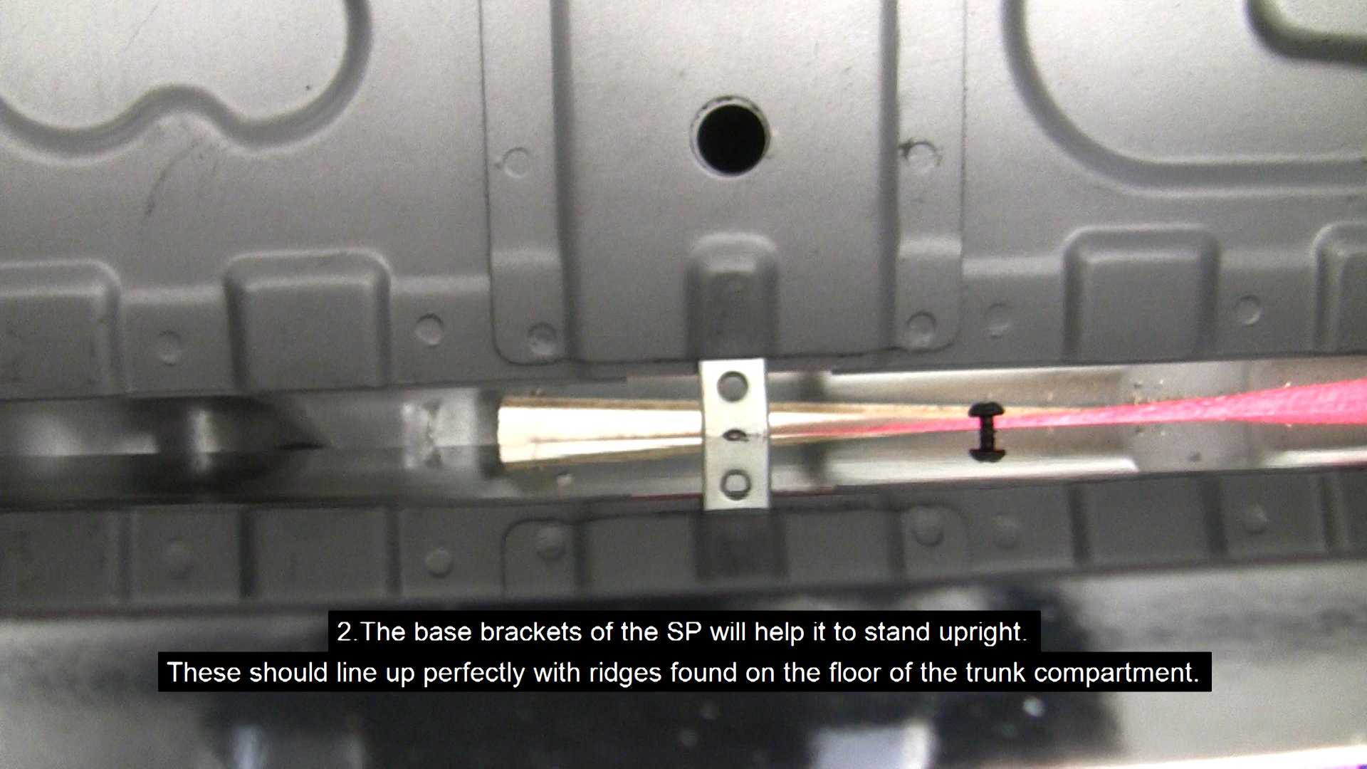
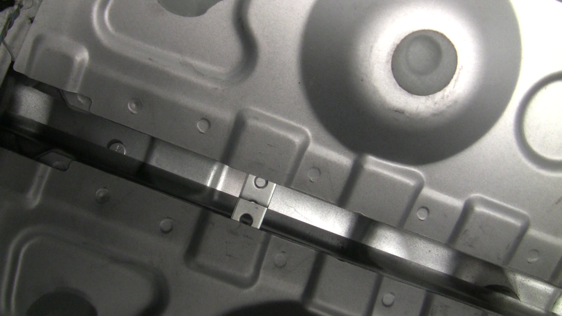
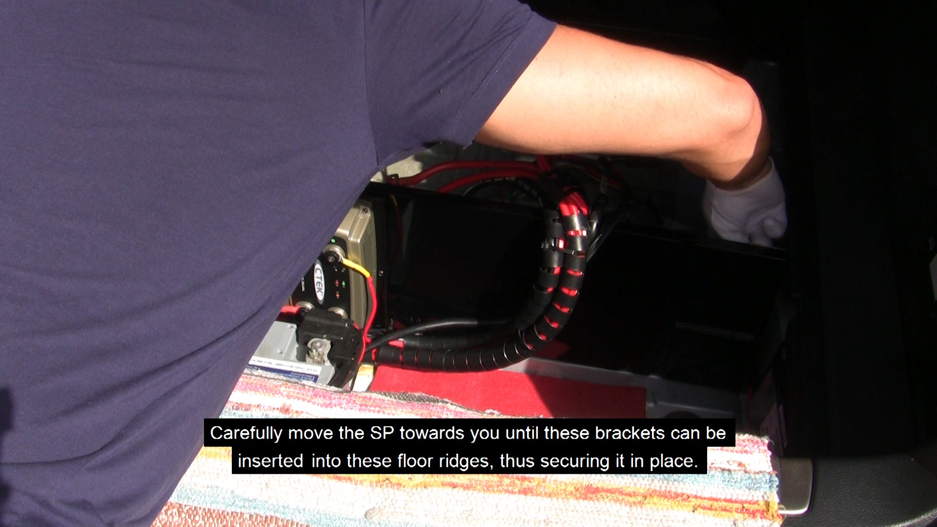
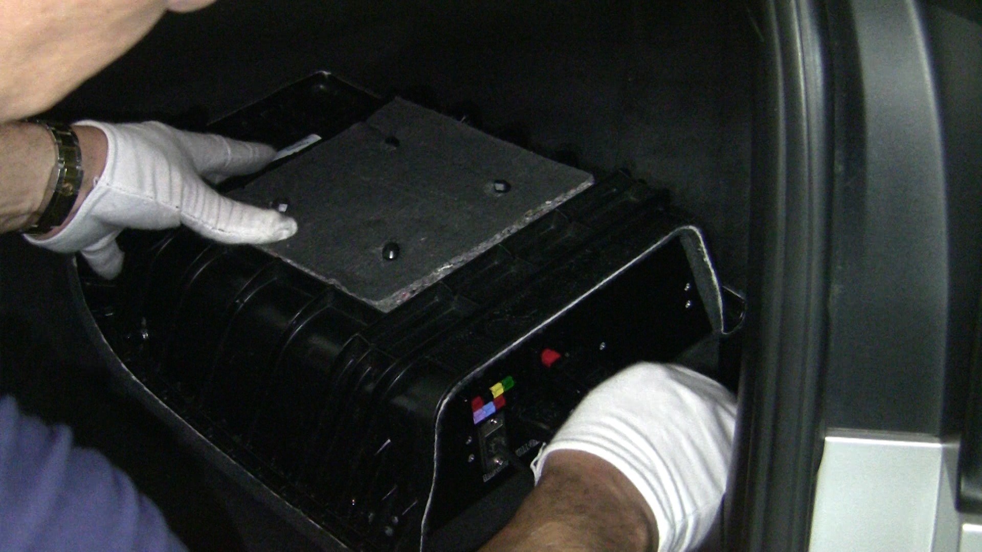
- The base brackets of the SP will help it to stand upright. These should line up perfectly with ridges found on the floor of the trunk compartment. Carefully move the SP towards you until these brackets can be inserted into these floor ridges, thus holding it in place.
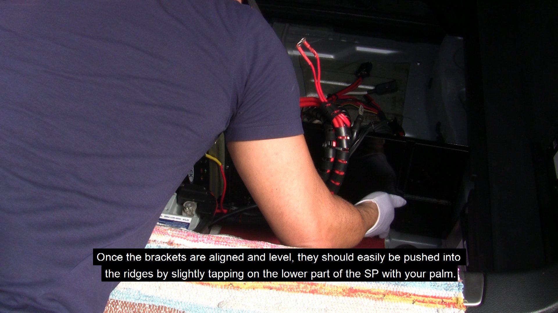
CAUTION: Do not place too much force or you can break the brackets off the panel. Once the brackets are aligned and level, they should easily be pushed into the ridges by slightly tapping on the lower middle part of the SP with your palm.
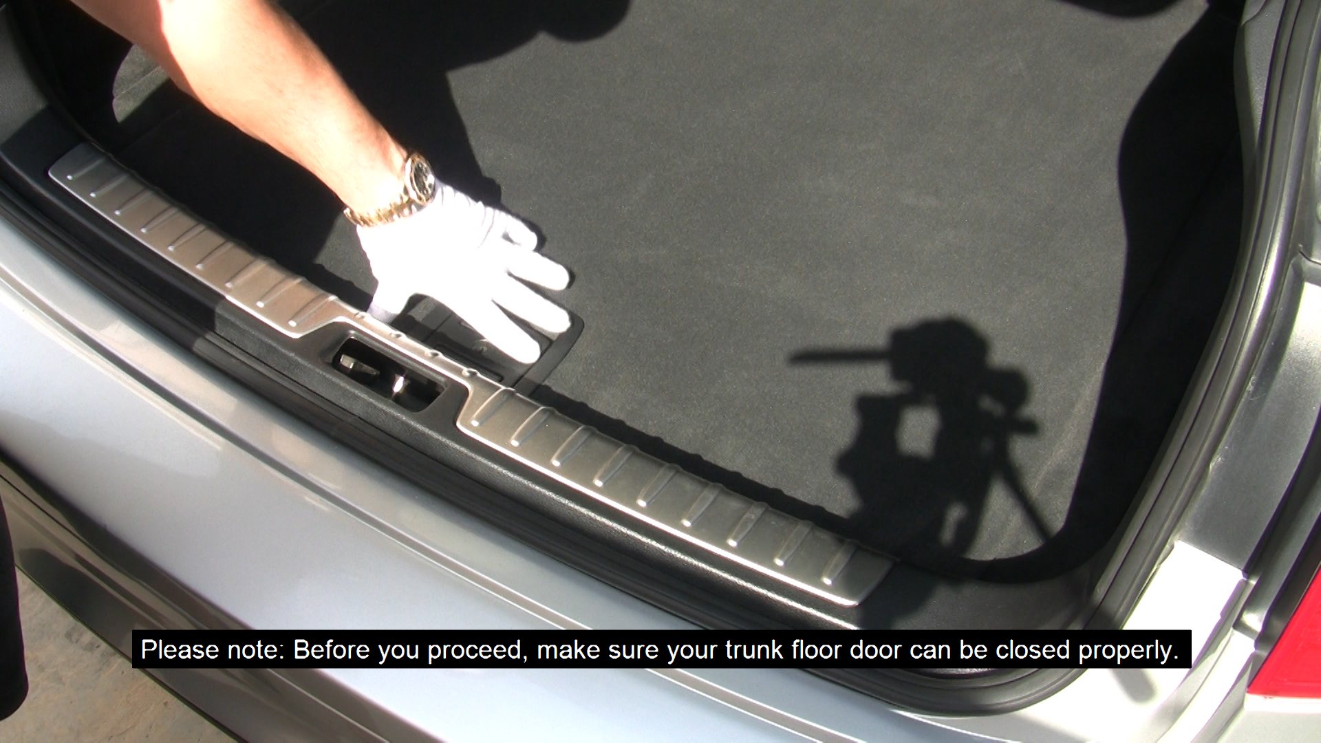
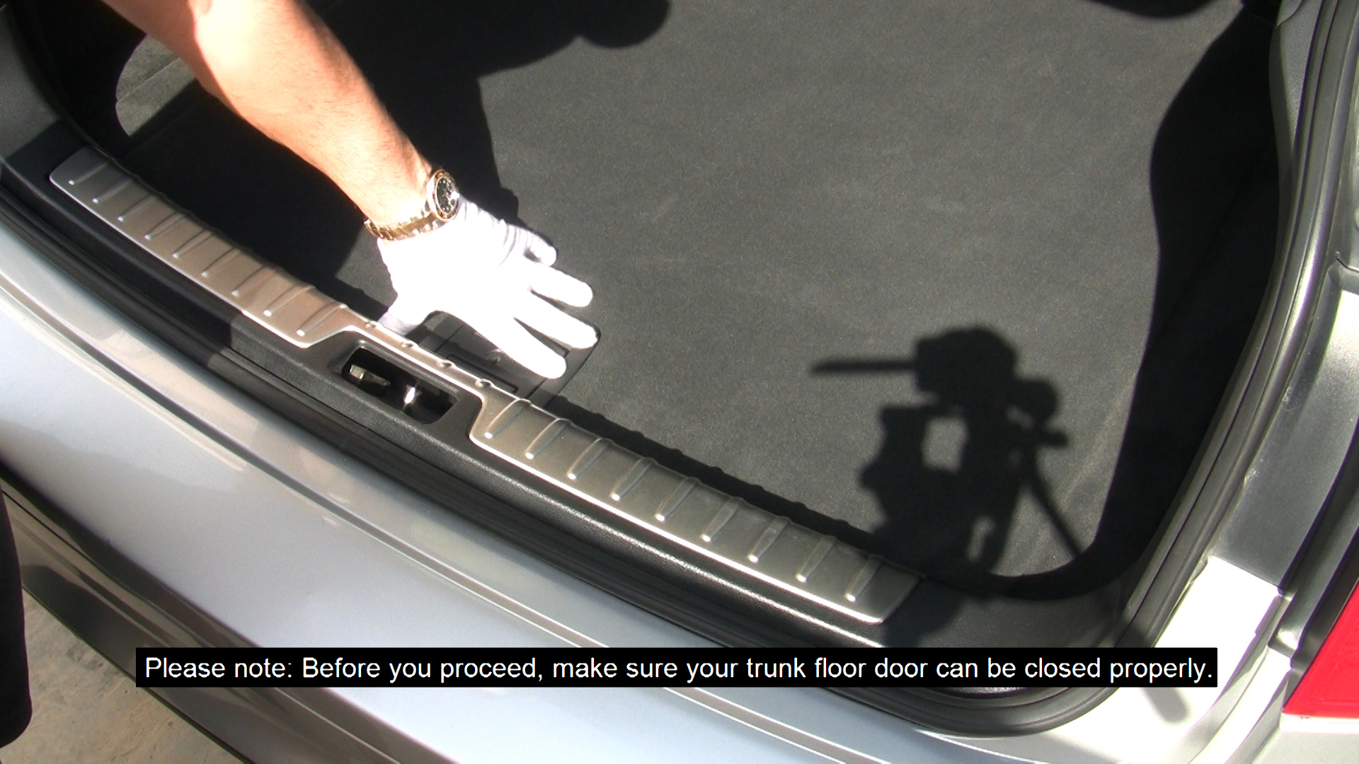
WARNING: Before you proceed, make sure your trunk floor door can be closed properly. If you find that the trunk floor door needs a lot of effort to close properly, then you need to recheck your installation for problems. If you have followed closely the above steps, there should be no problems closing the floor door.
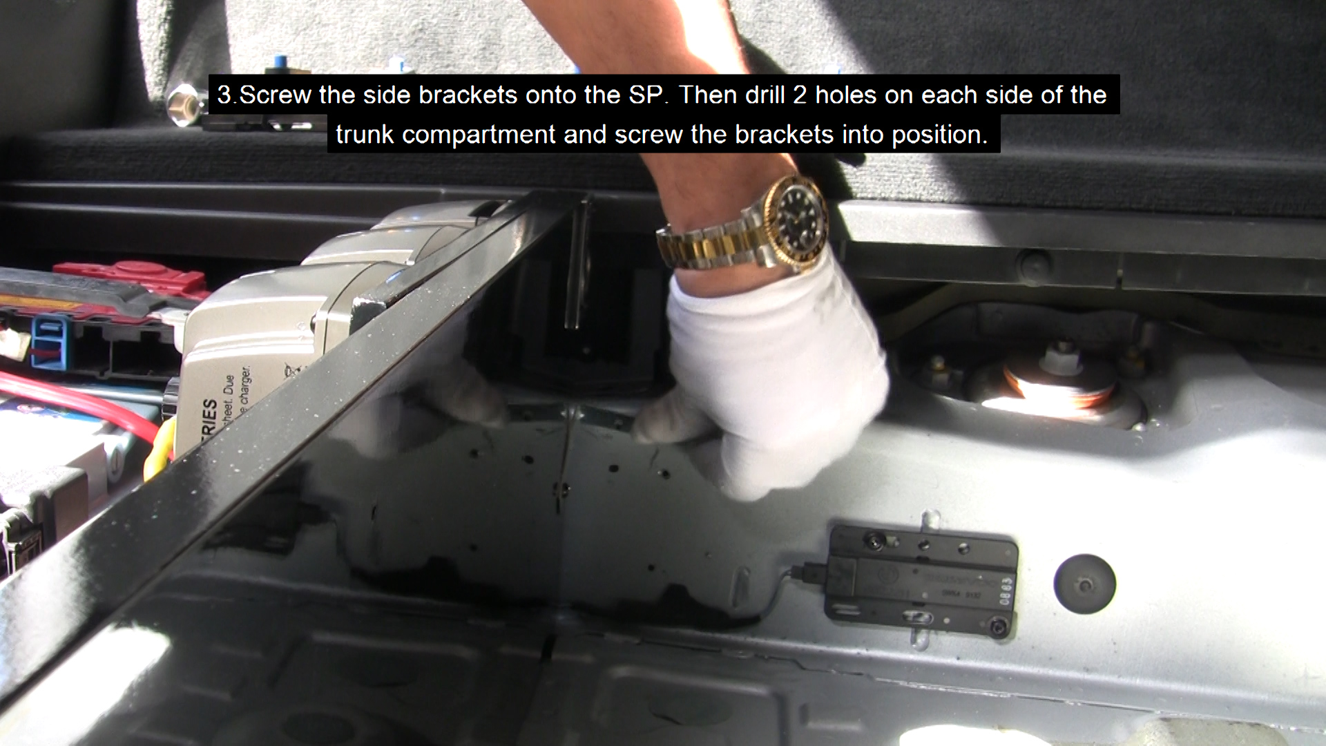
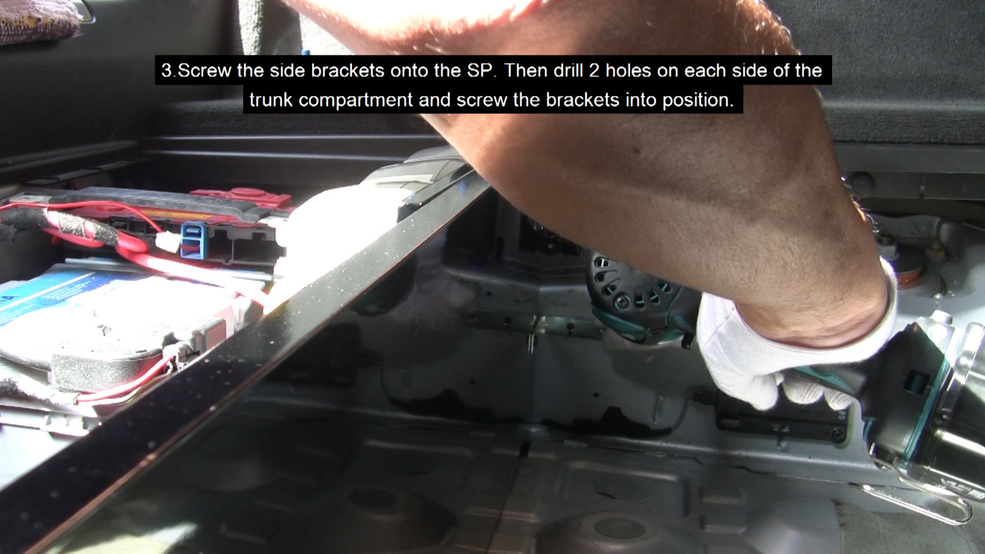
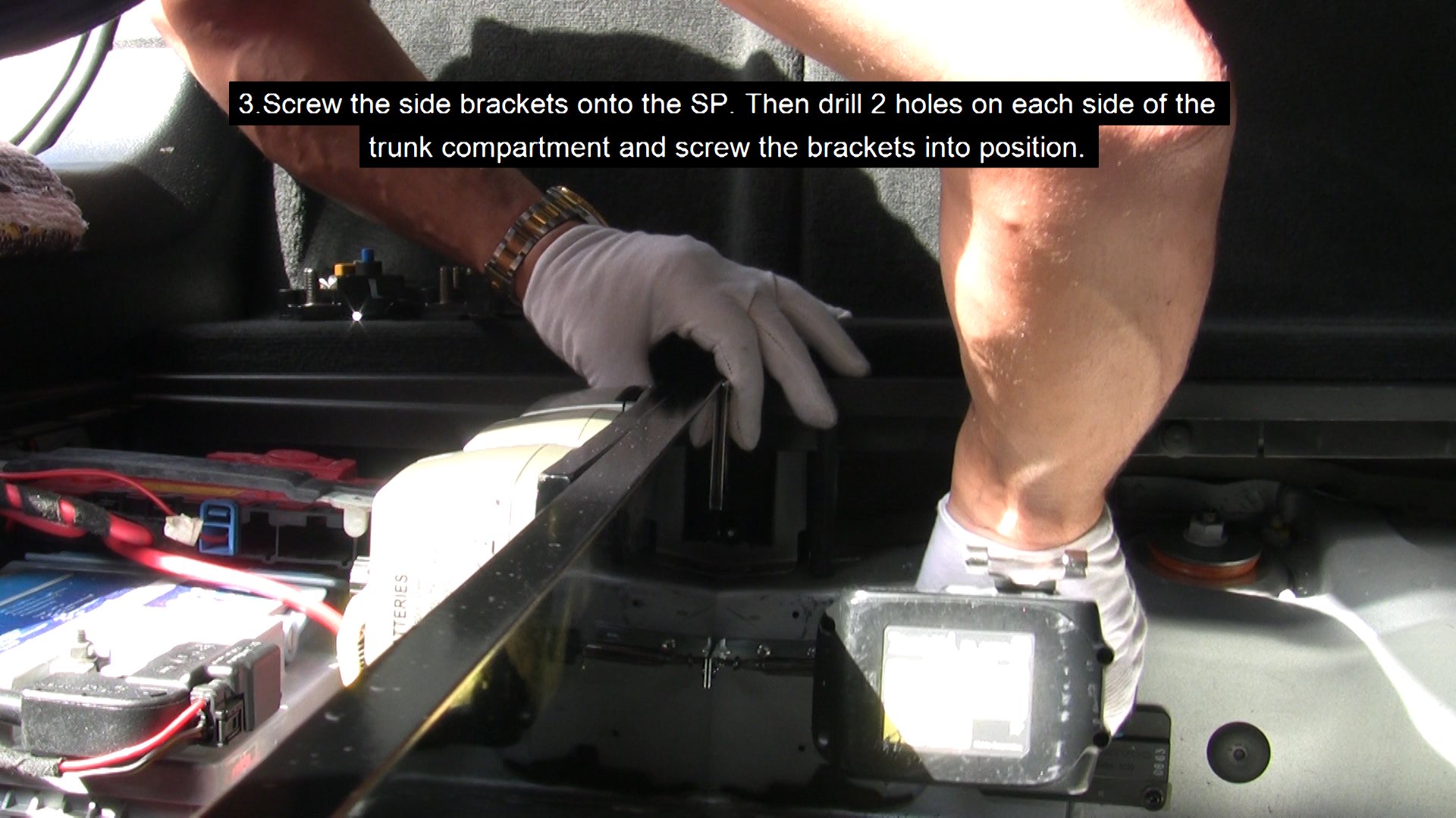
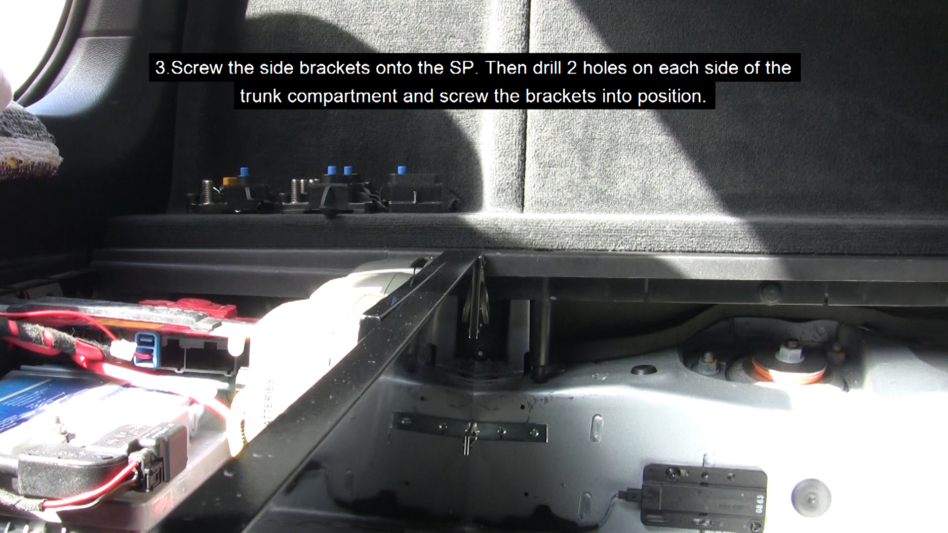
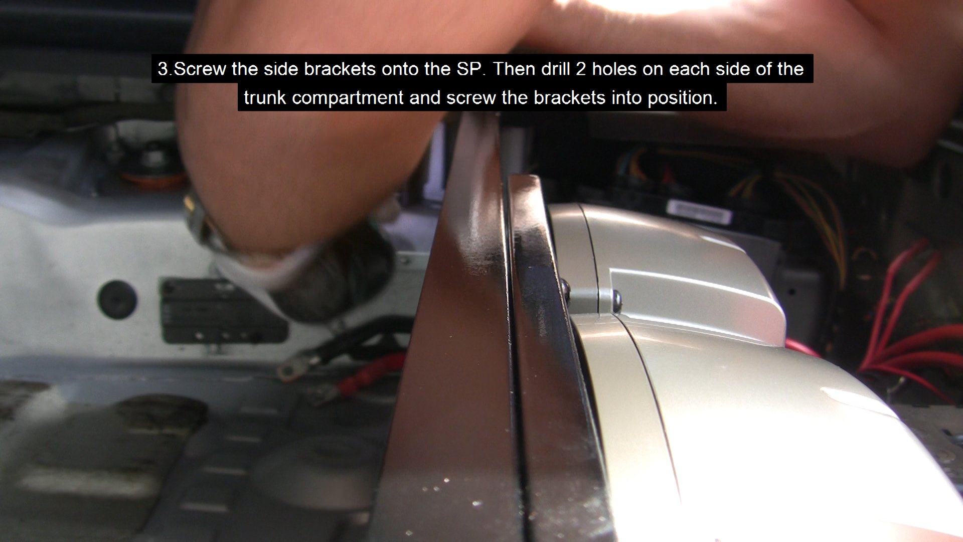
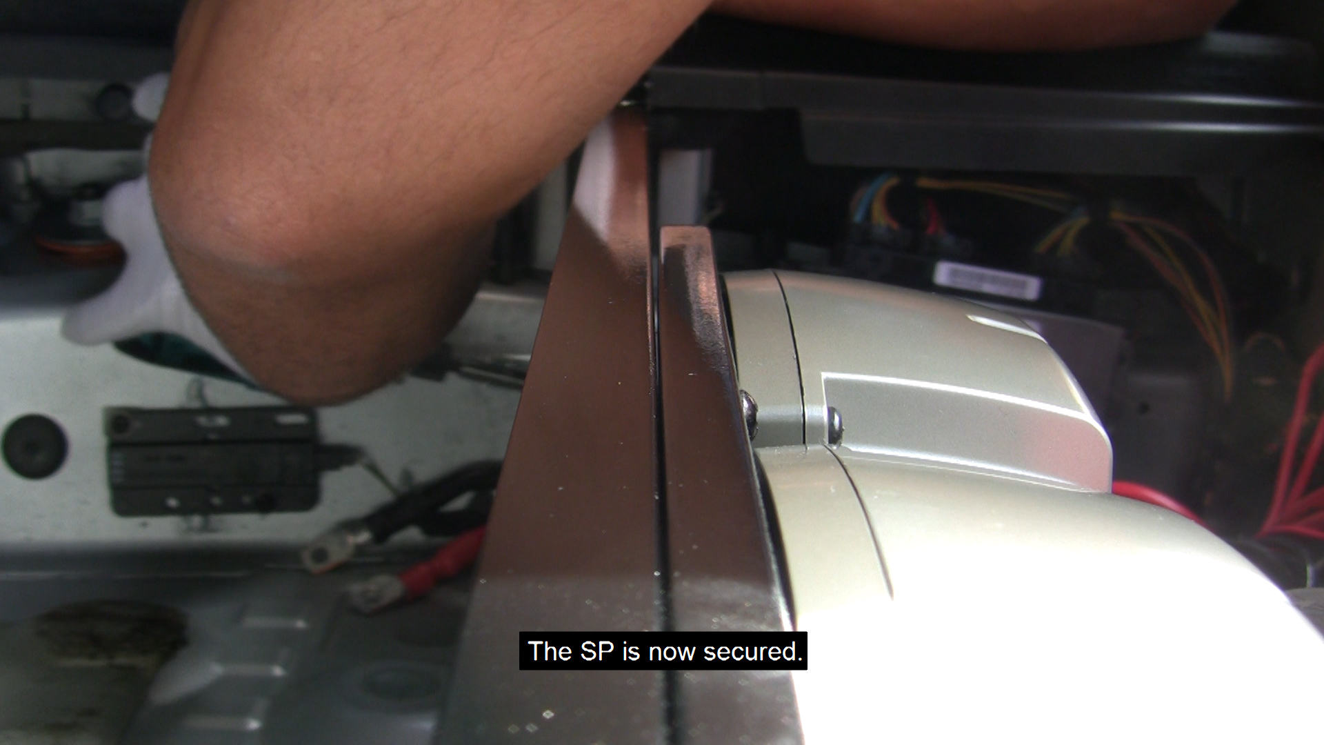
- Screw the side brackets onto the SP. Then drill 2 holes on each side of the trunk compartment and screw the brackets into position. The SP is now secured.
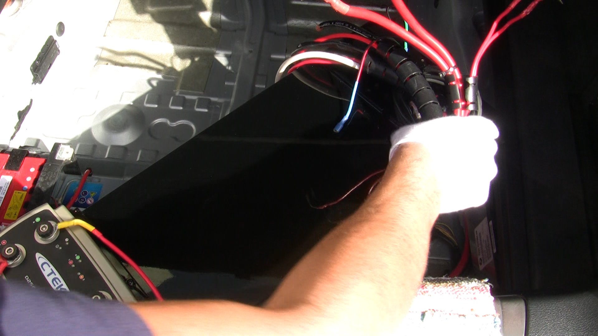
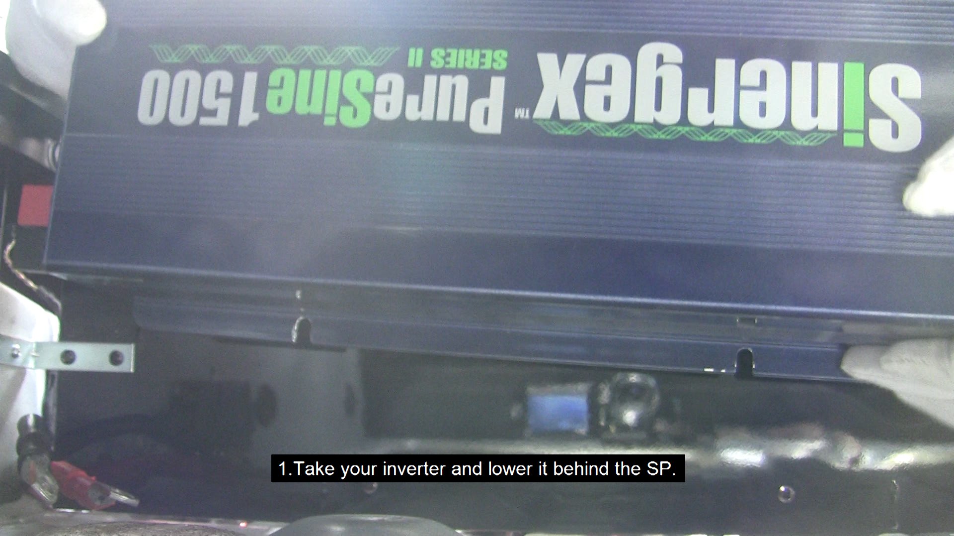
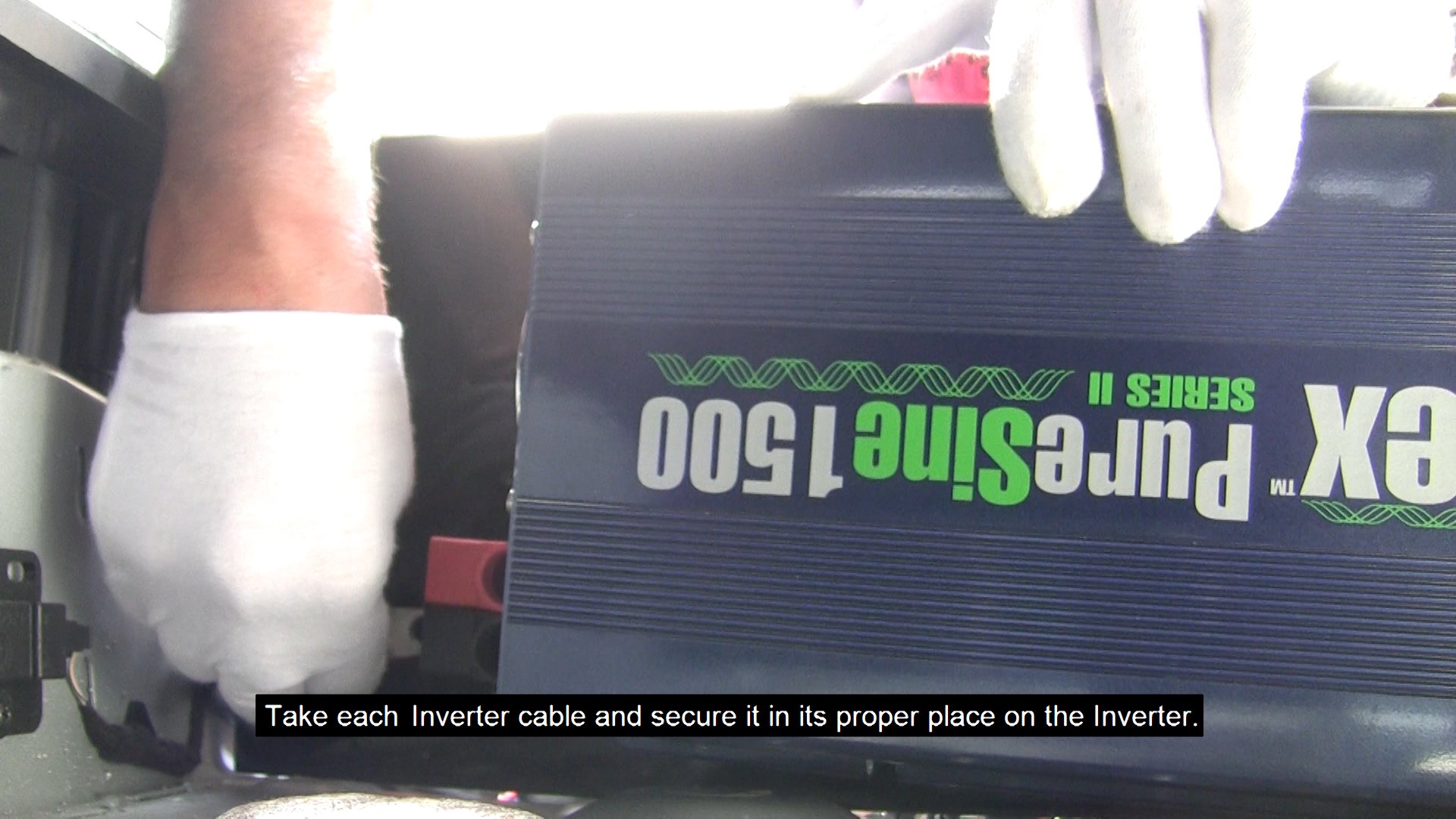
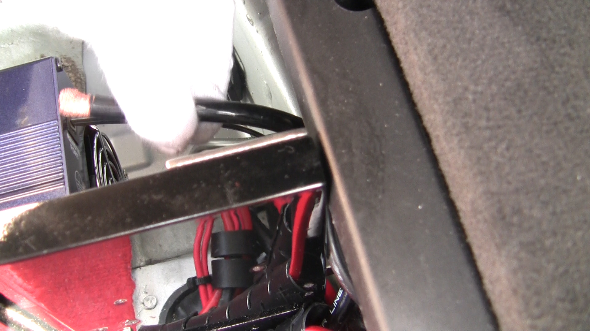
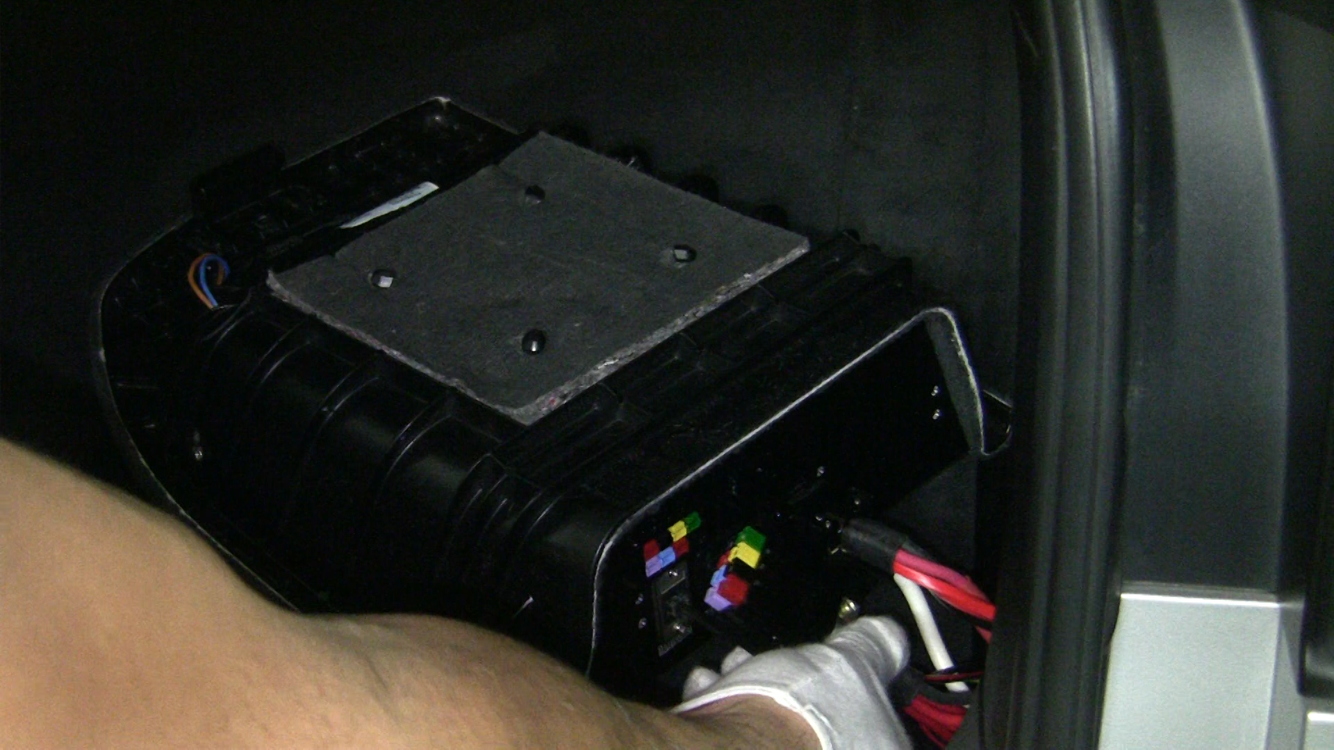
- Take your inverter and lower it behind the SP without fastening it. Now take each Inverter cable and secure it in its proper place on the Inverter.
Please note: You may want to place the Inverter on a soft rug to avoid scratching it on the trunk floor.
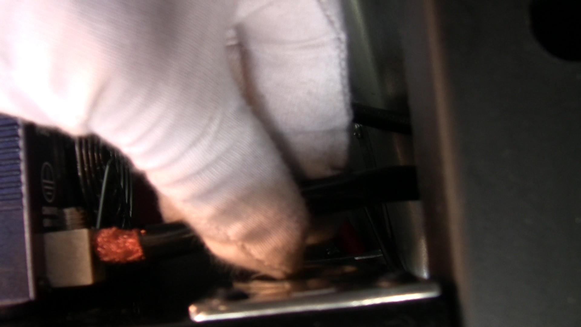
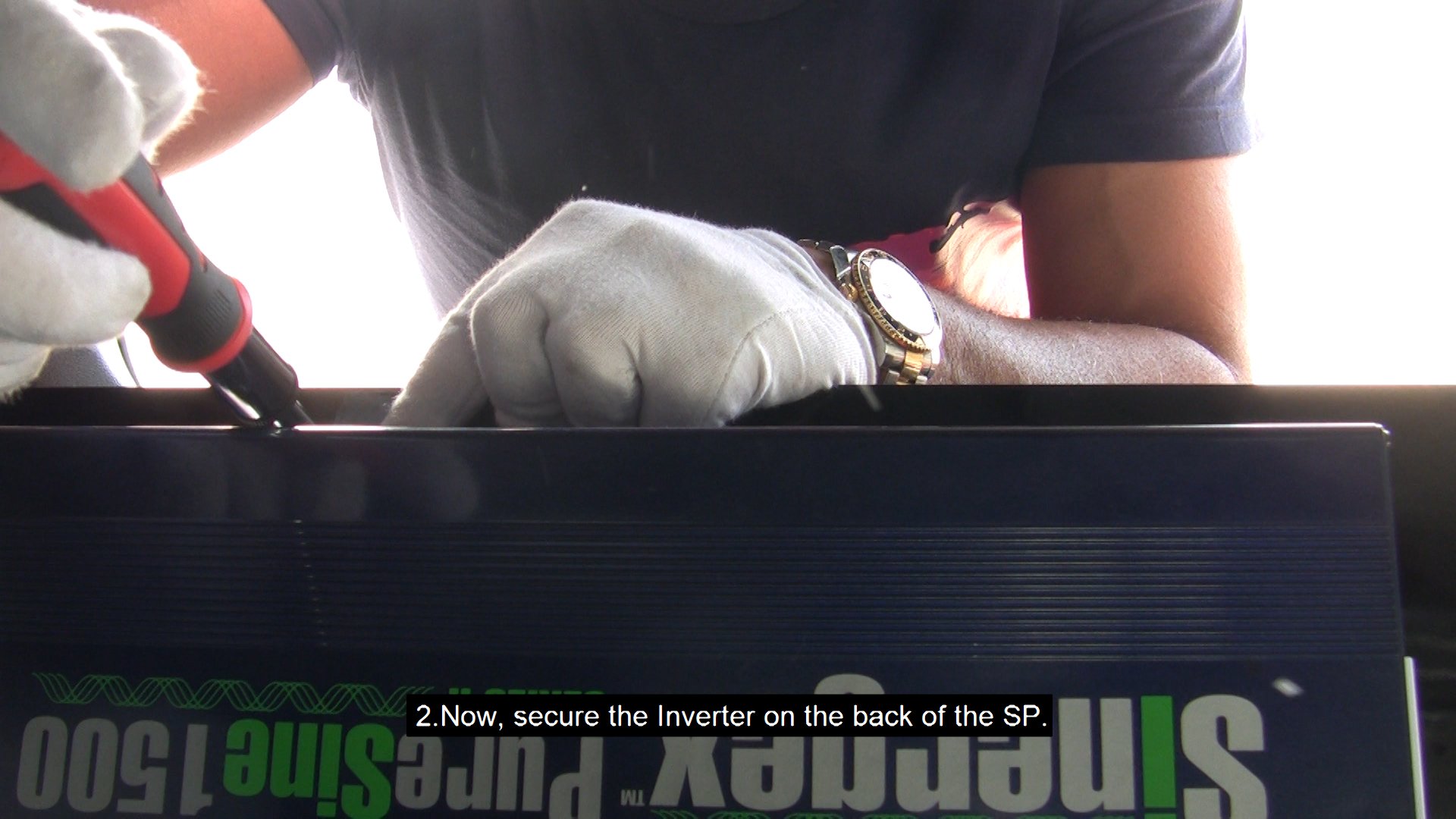
- Now, secure the Inverter on the back of the SP.
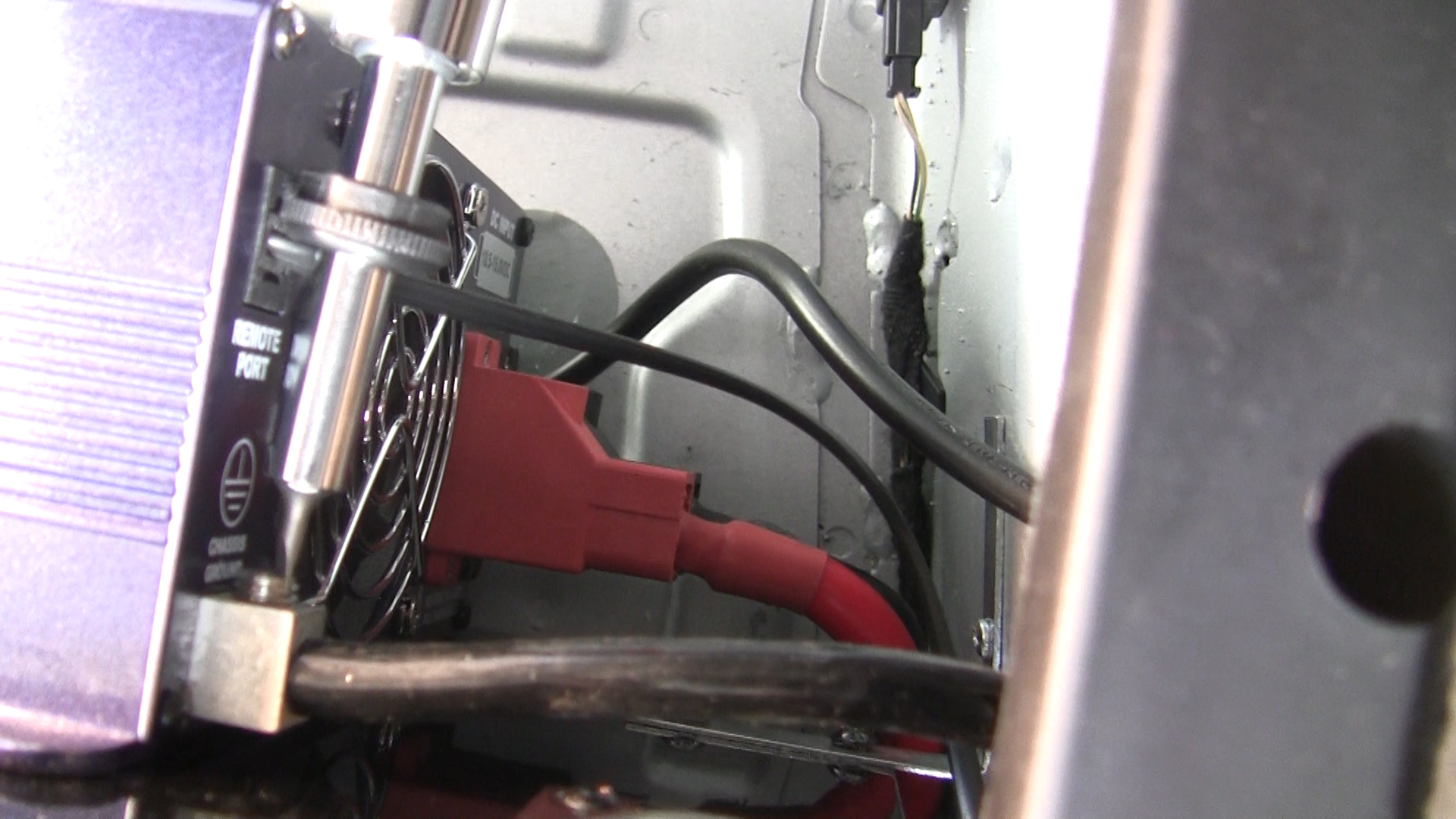
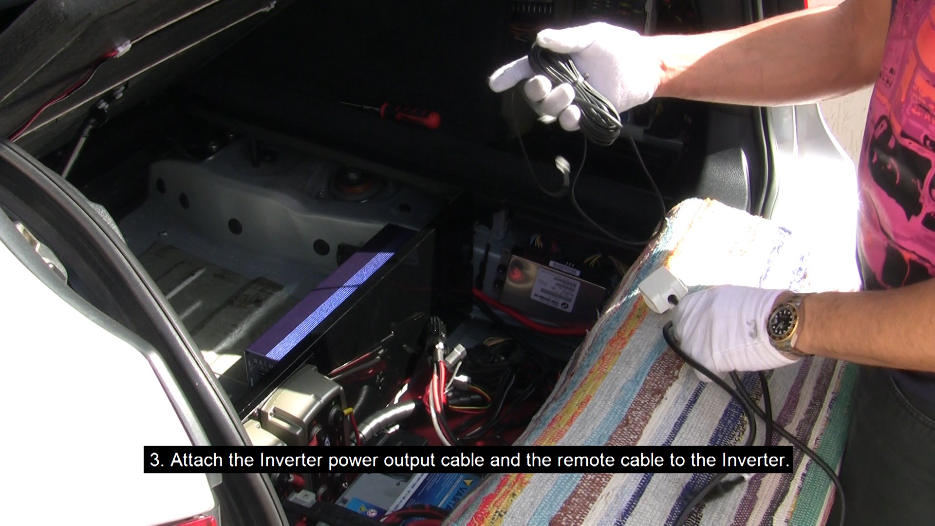
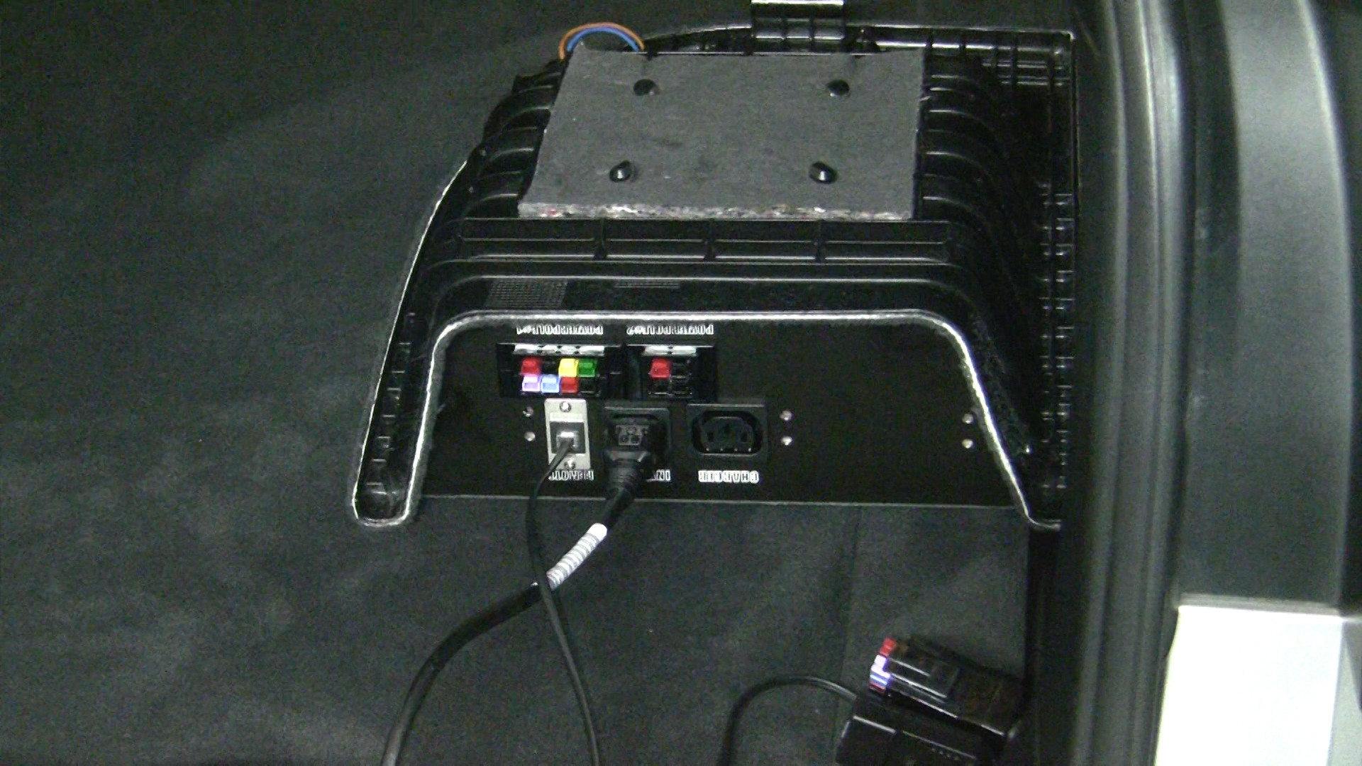
- Attach the Inverter power output cable and the remote cable to the Inverter.
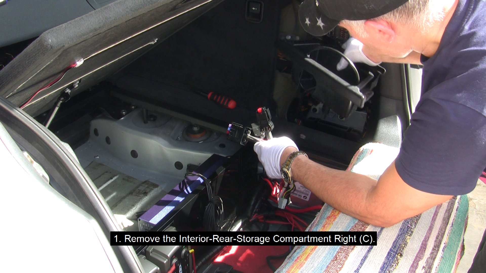
- Remove the Interior-Rear-Storage Compartment Right (C).
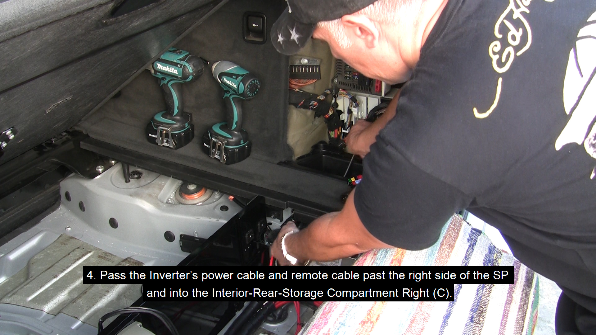
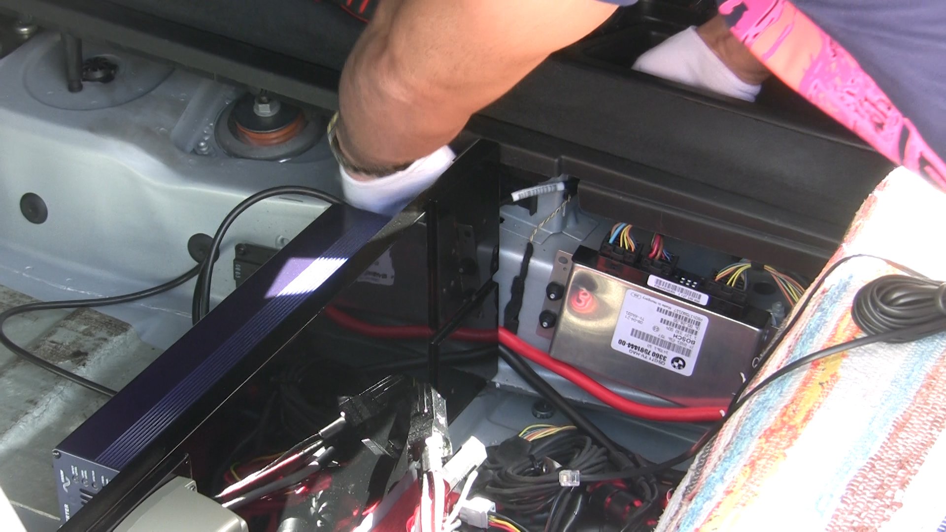
- Pass the Inverter’s power cable and remote cable past the right side of the SP and into the area where the Interior-Rear-Storage Compartment Right (C) used to sit. Leave them loose there for now.
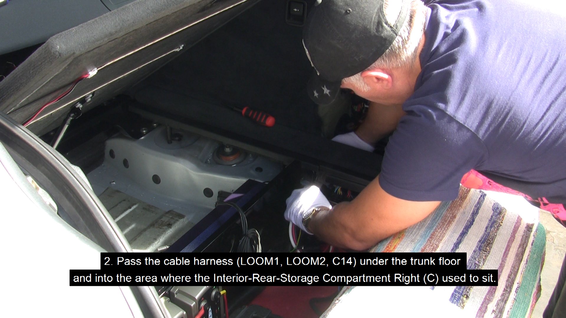
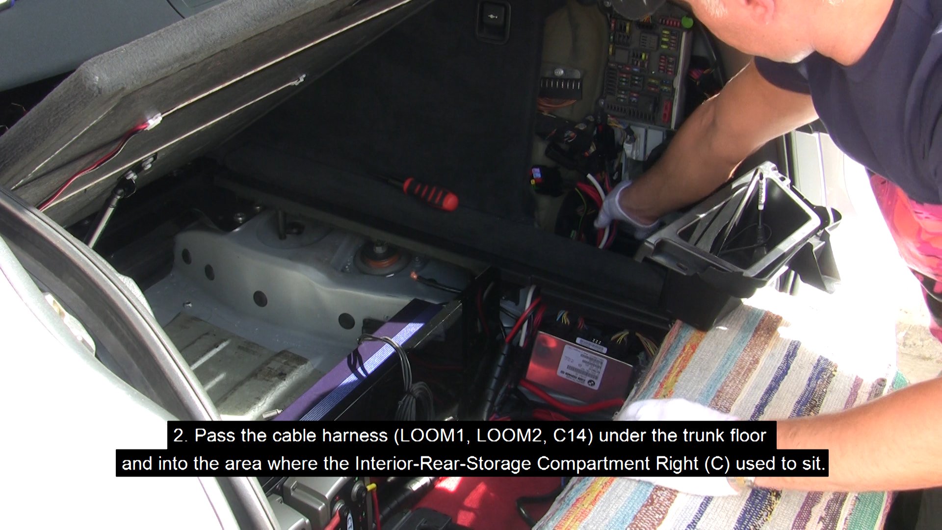
- Pass the cable harness (LOOM1, LOOM2, C14) under the trunk floor and into the area where the Interior-Rear-Storage Compartment Right (C) used to sit.
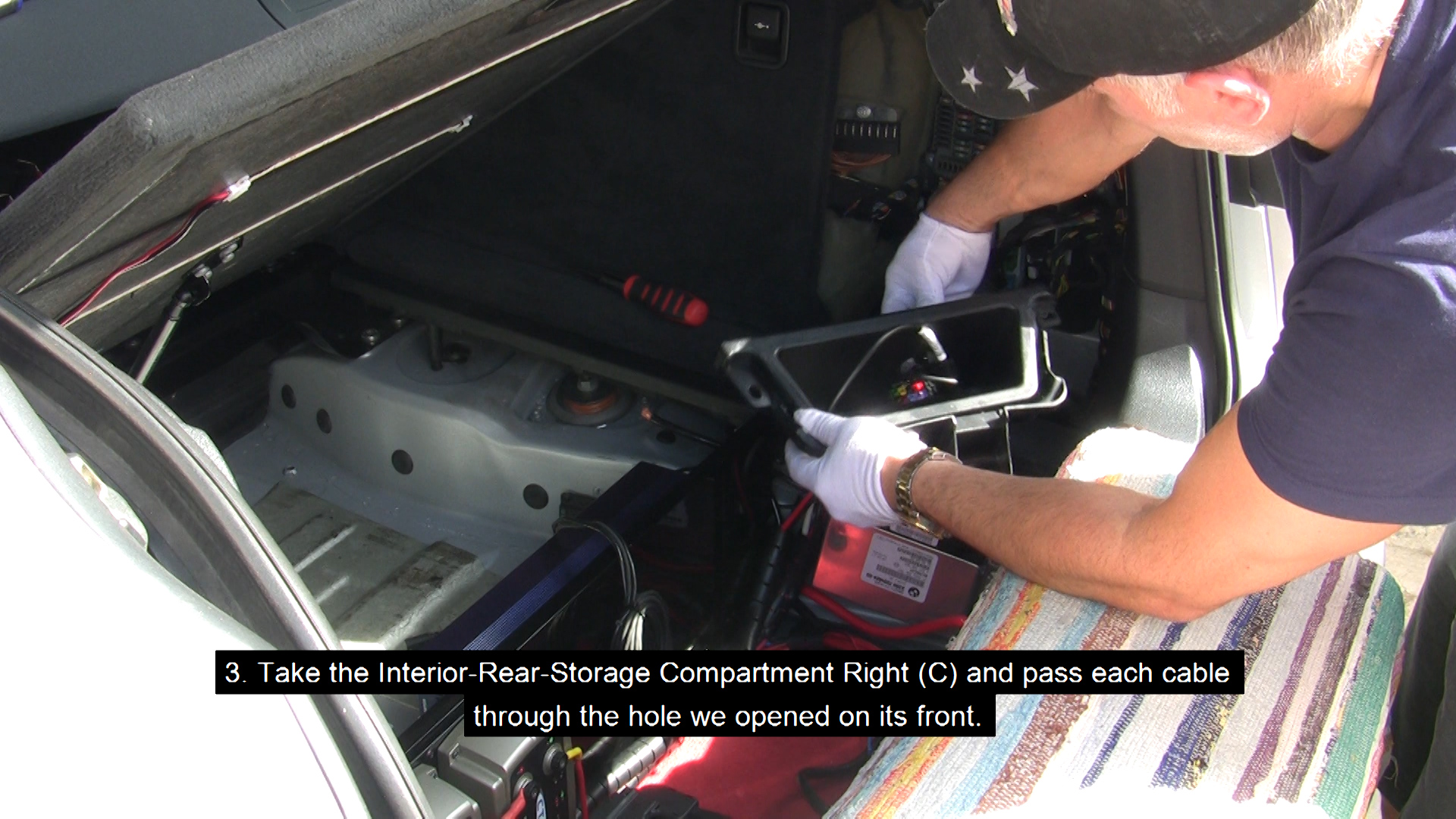
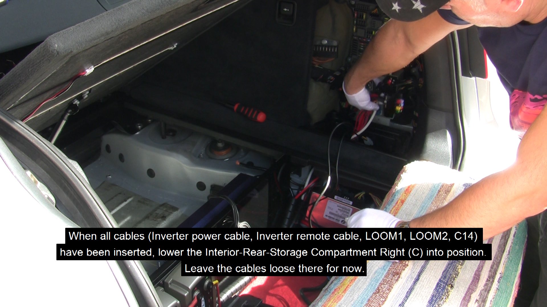
- Take the Interior-Rear-Storage Compartment Right (C) and pass each cable through the hole we opened on its front. When all cables (Inverter power cable, Inverter remote cable, LOOM1, LOOM2, C14) have been inserted, lower the Interior-Rear-Storage Compartment Right (C) back into position. Leave the cables loose there for now.
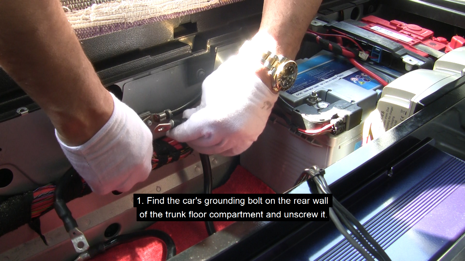
- Find the car's grounding bolt on the rear wall of the trunk floor compartment and unscrew it.
CAUTION: Do not remove the cables connected, or your car will reset. This is not a big deal if it happens though. You may just have to re-set some of your settings like the time etc.
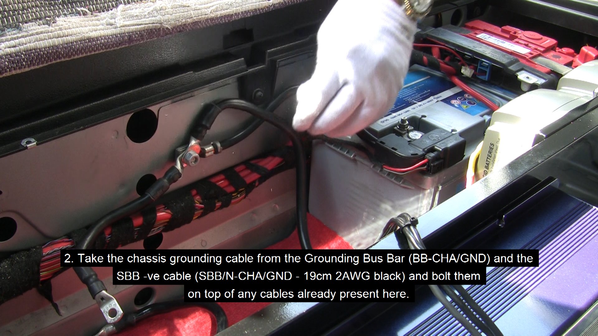
- Take the chassis grounding cable from the Grounding Bus Bar (BB-CHA/GND) and the
SBB -ve cable (SBB/N-CHA/GND - 19cm 2AWG black) and bolt them on top of any cables already present here.
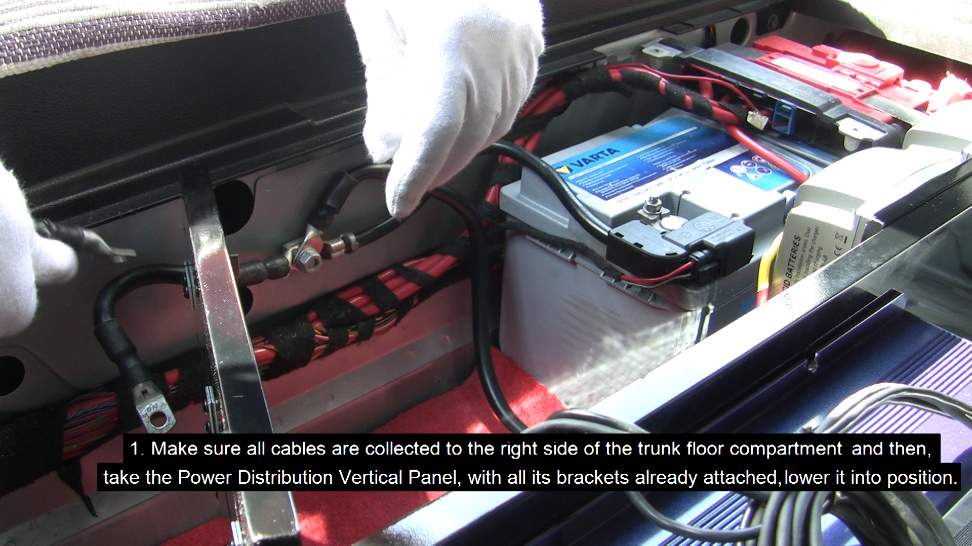
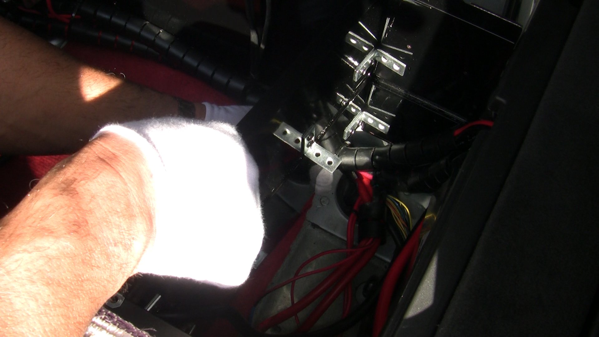
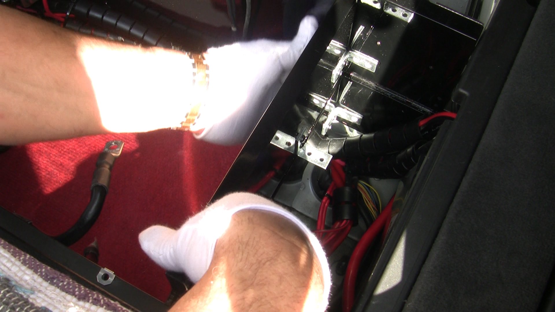
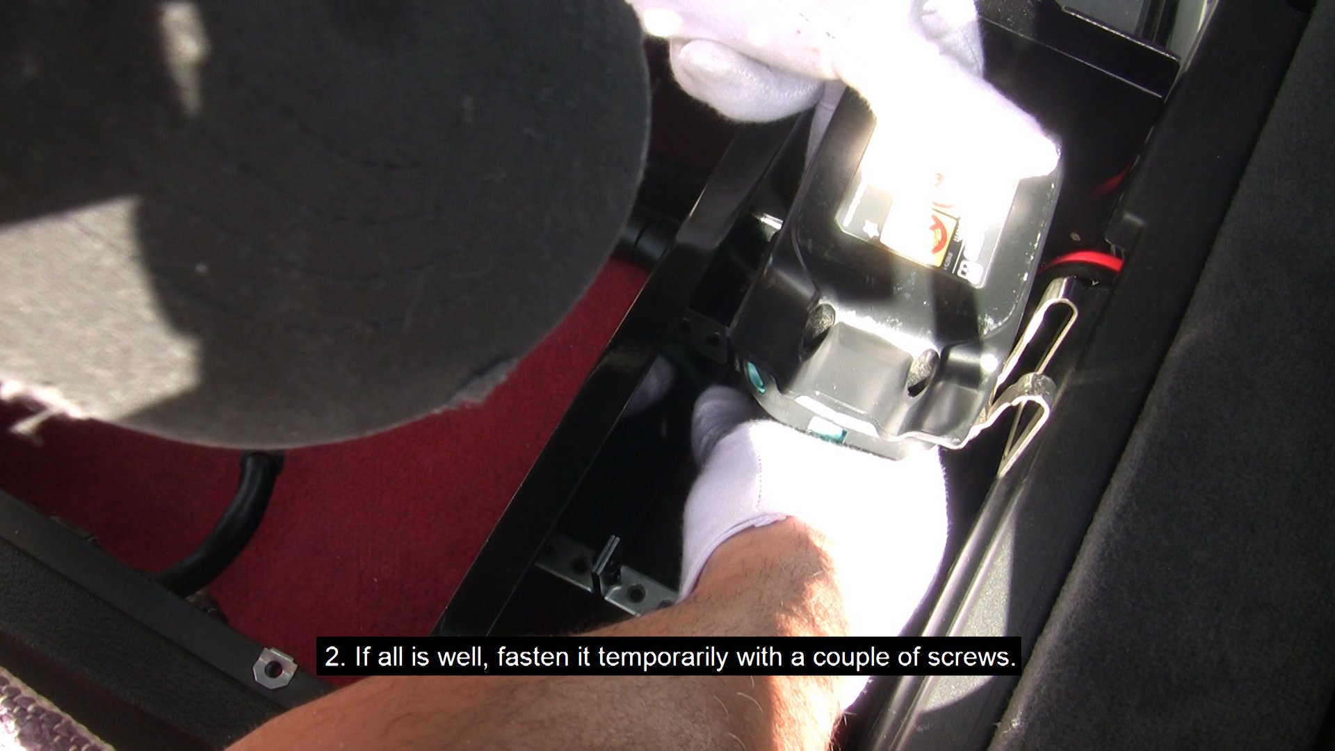
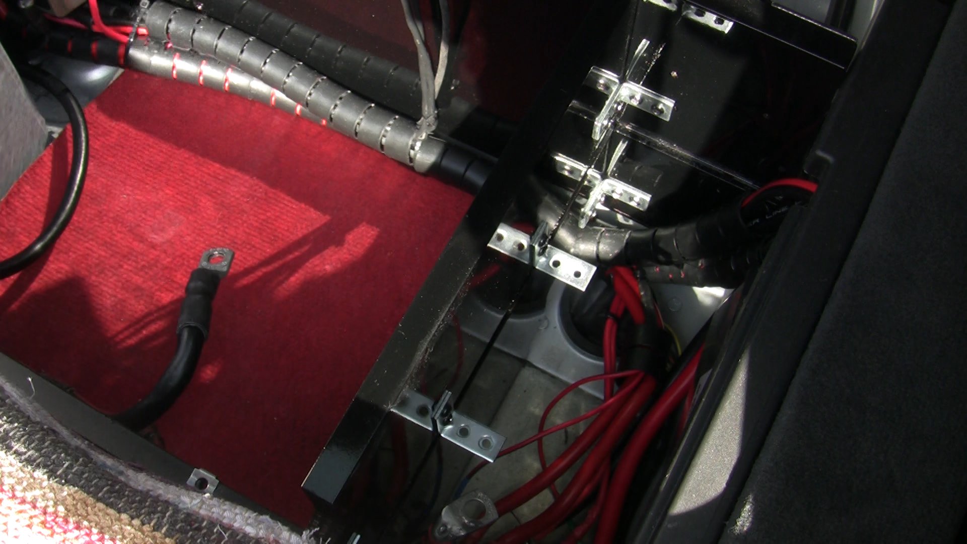
- Make sure all cables are collected to the right side of the trunk floor compartment and then, take the Power Distribution Vertical Panel, with all its brackets already attached, lower it into position and fasten it temporarily with a couple of screws.
WARNING: Before you proceed, make sure your trunk floor door can be closed properly. If you find that the trunk floor door needs a lot of effort to close properly, then you need to recheck your installation for problems. If you have followed closely the above steps, there should be no problems closing the floor door.
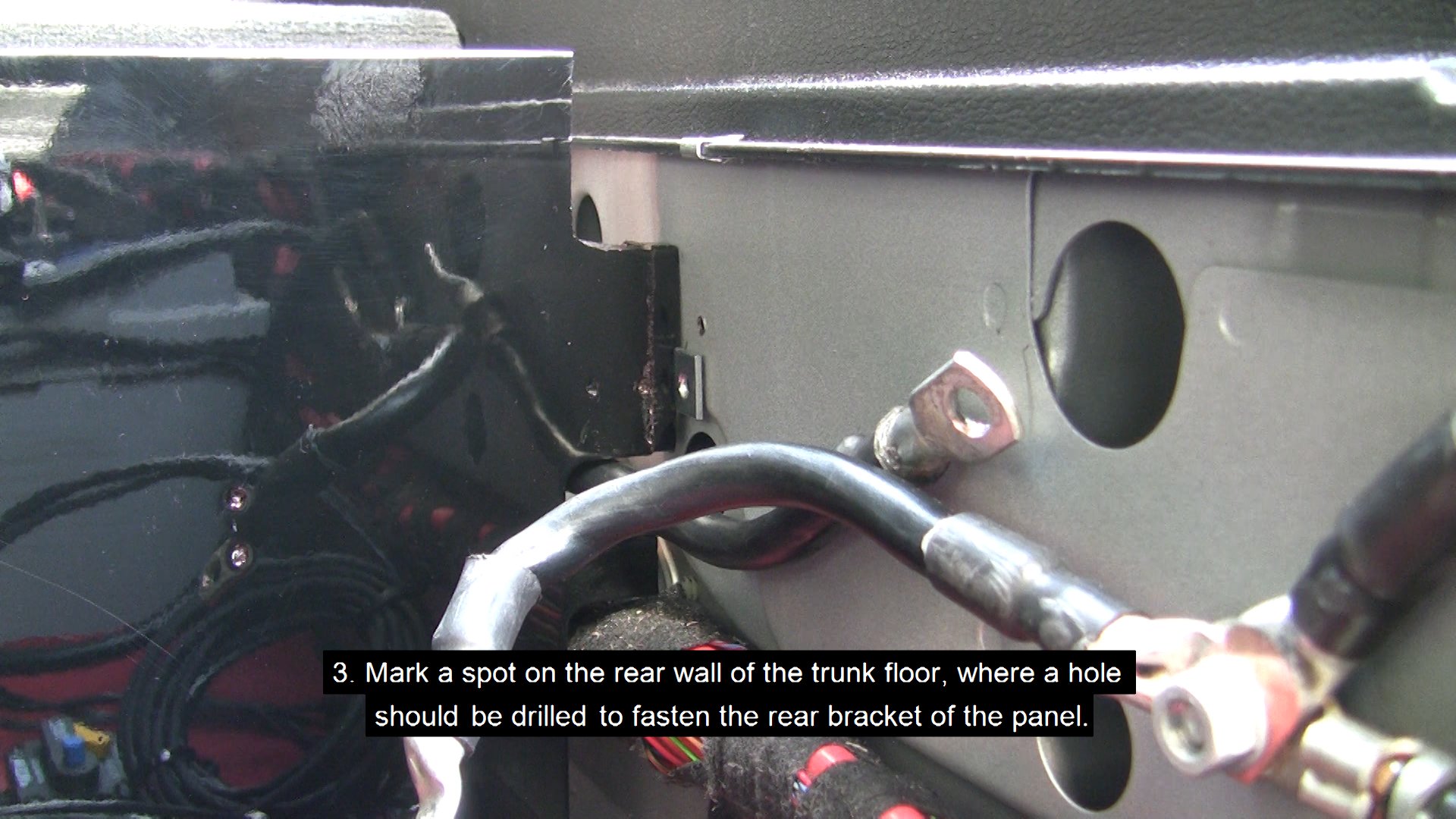
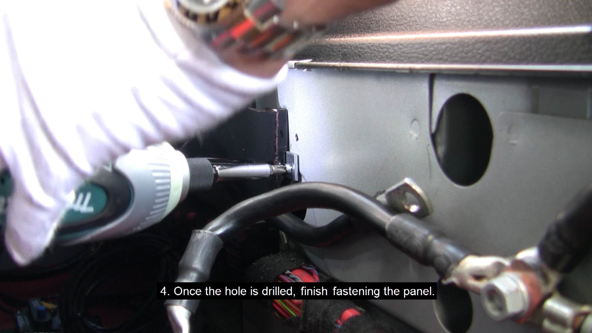
- If all is well, take a marker and mark a spot on the rear wall of the trunk floor, where a hole should be drilled to fasten the rear bracket of the Power Distribution Vertical Panel. Apply enough force onto the top part of the Power Distribution Vertical Panel until it sits at its lowest level. (You may need to remove the Power Distribution Vertical Panel in order to drill the hole, otherwise go ahead).
- Once the hole is drilled finish fastening the Power Distribution Vertical Panel to the SP and the rear of the trunk floor compartment wall.
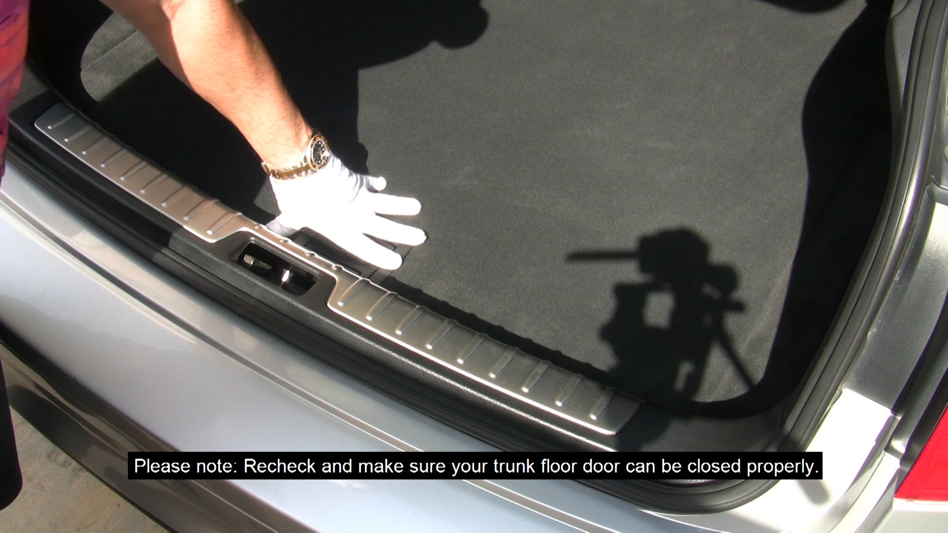
WARNING: Recheck and make sure your trunk floor door can be closed properly.
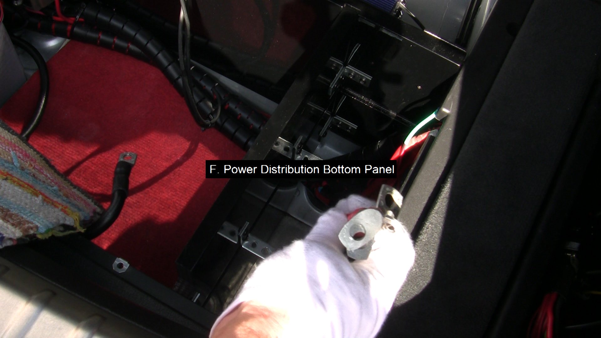
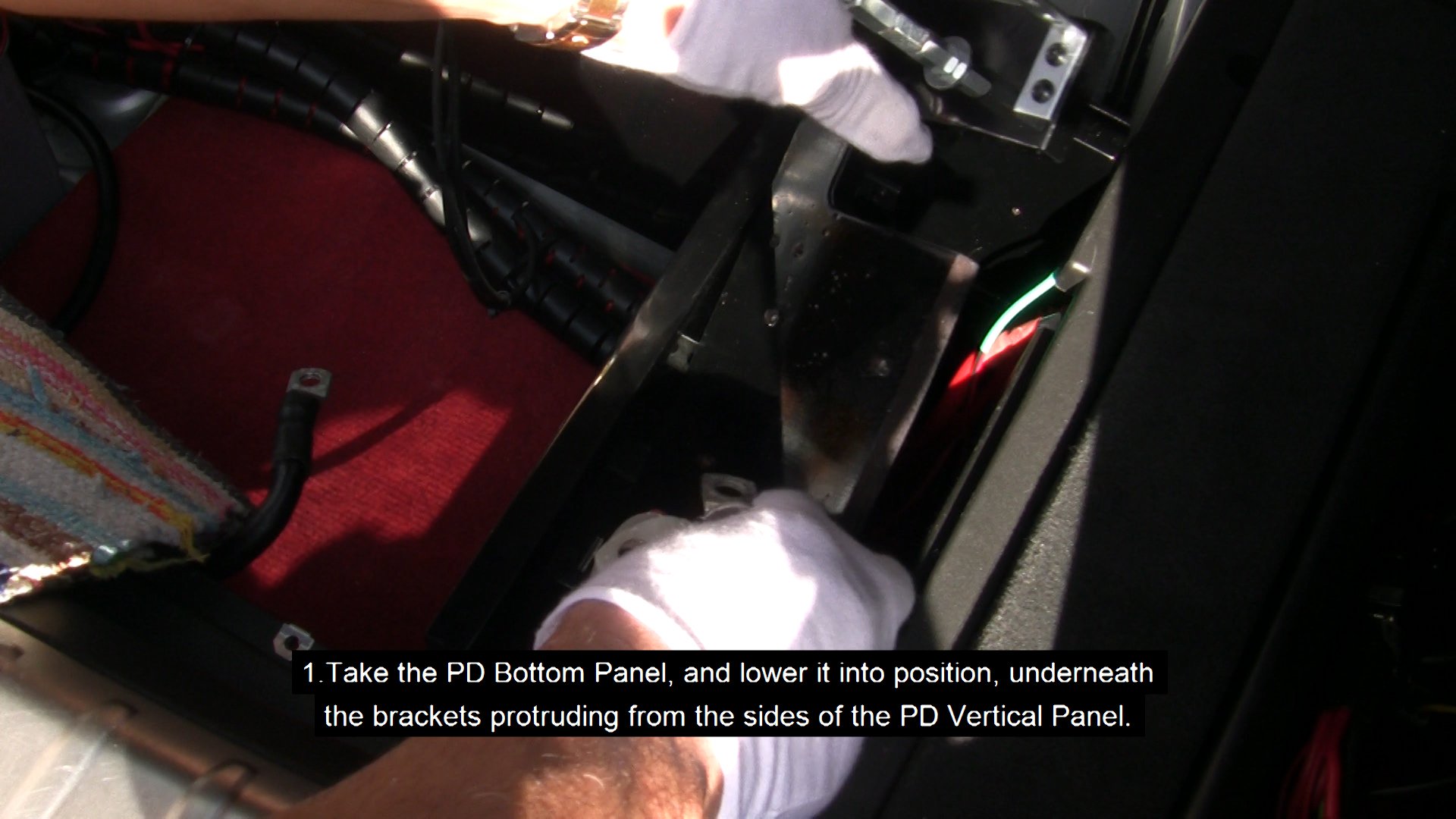
- Then take the Power Distribution Bottom Panel, and lower it into position, underneath the brackets protruding from the sides of the Power Distribution Vertical Panel. It should slide with minimal effort into the grooves of the SP and the Power Distribution Vertical Panel.
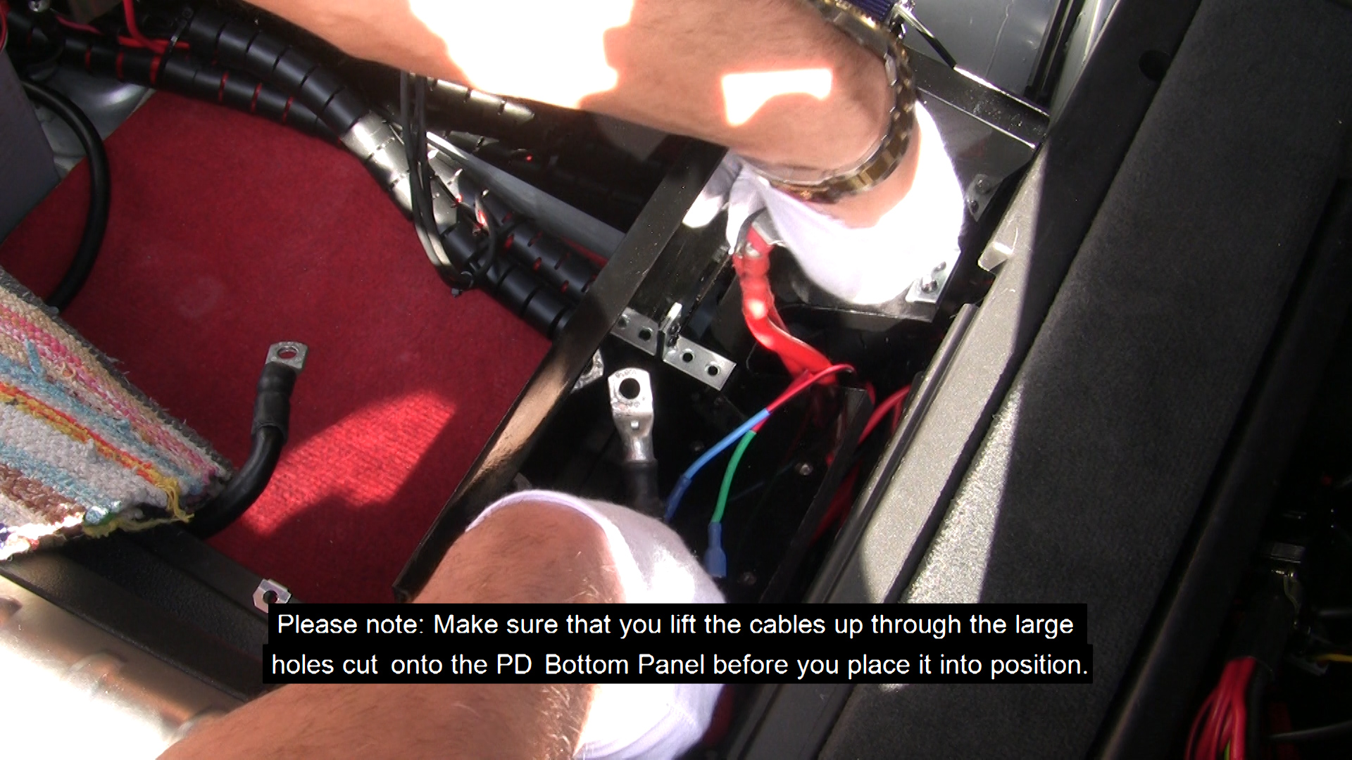
Please note: Make sure that you lift the cables up through the large holes cut onto the Power Distribution Bottom Panel before you place it into position. If required, use masking tape to prevent them from dropping back down.
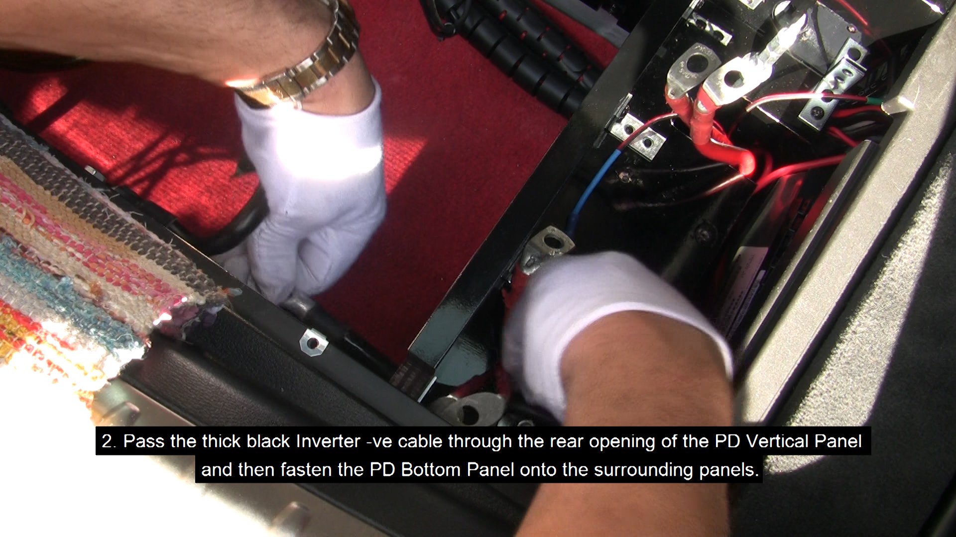
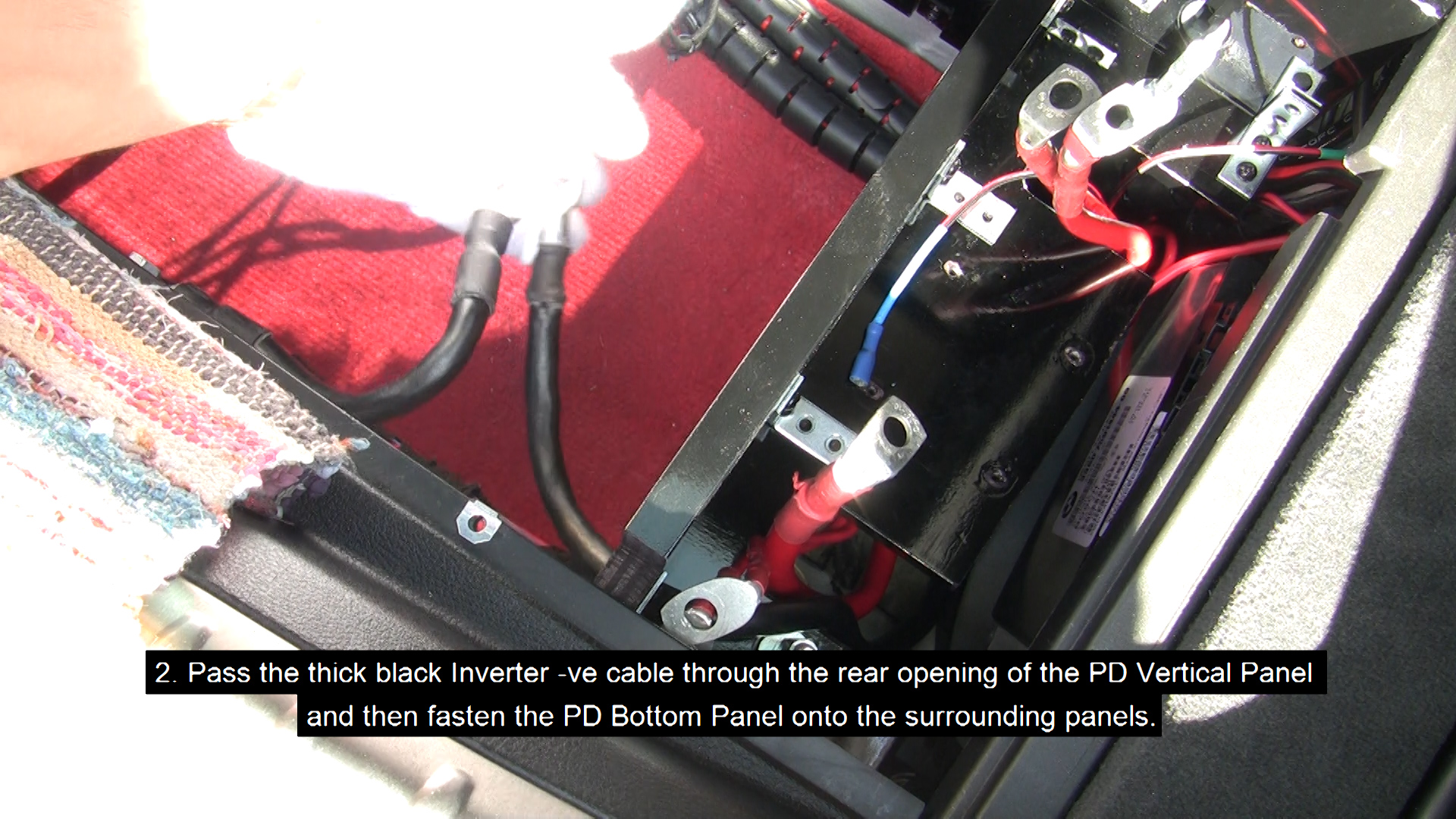
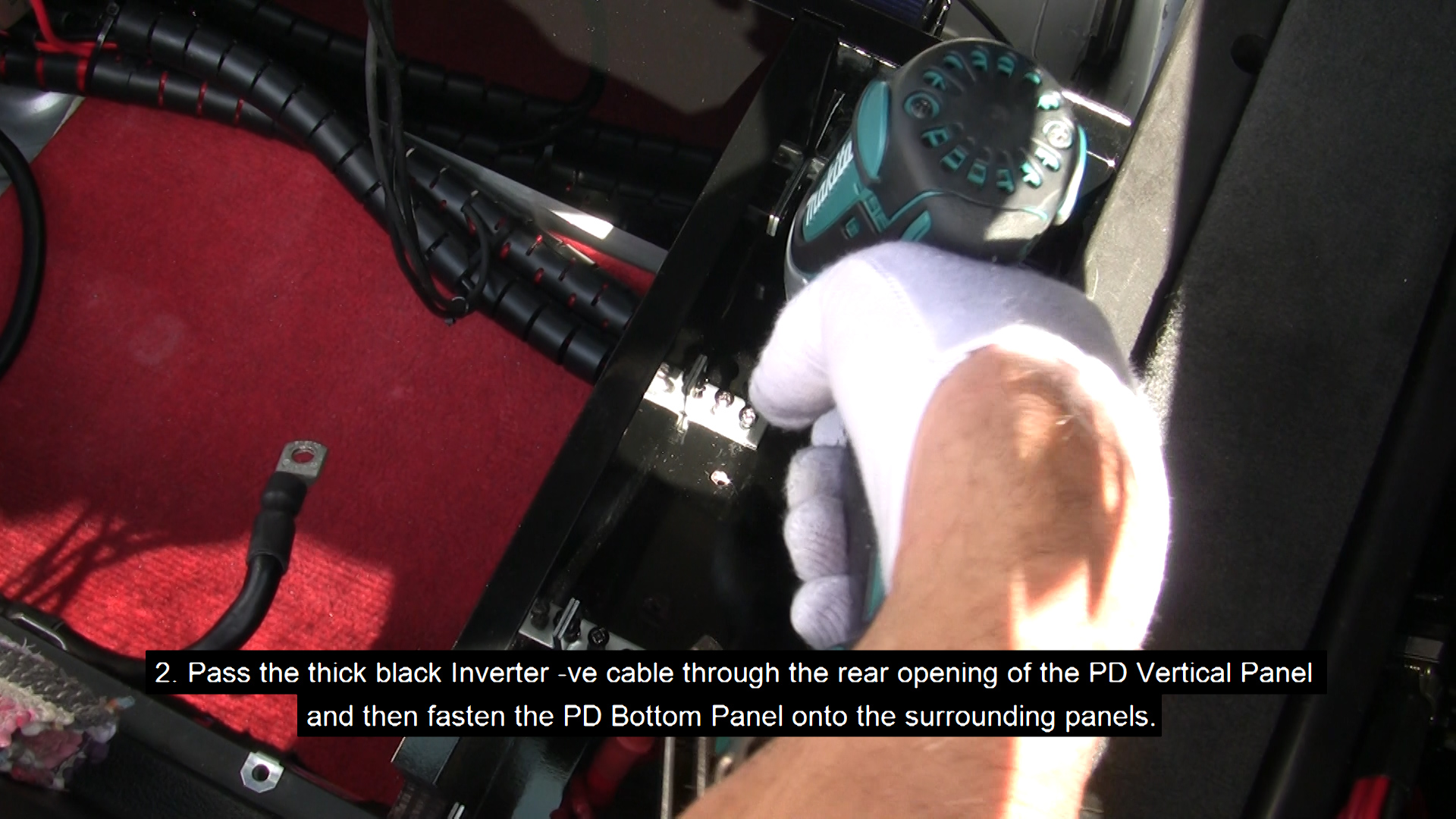
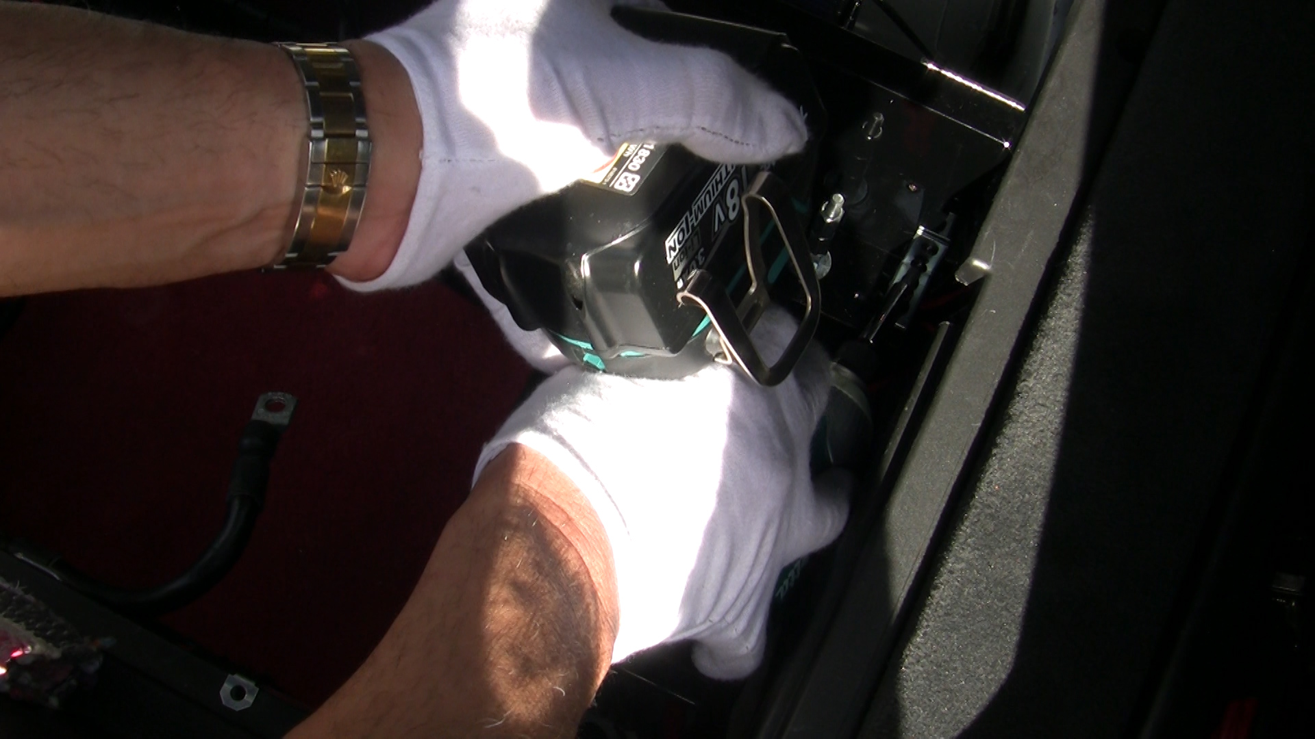
- Fasten the Power Distribution Bottom Panel onto the surrounding panels.
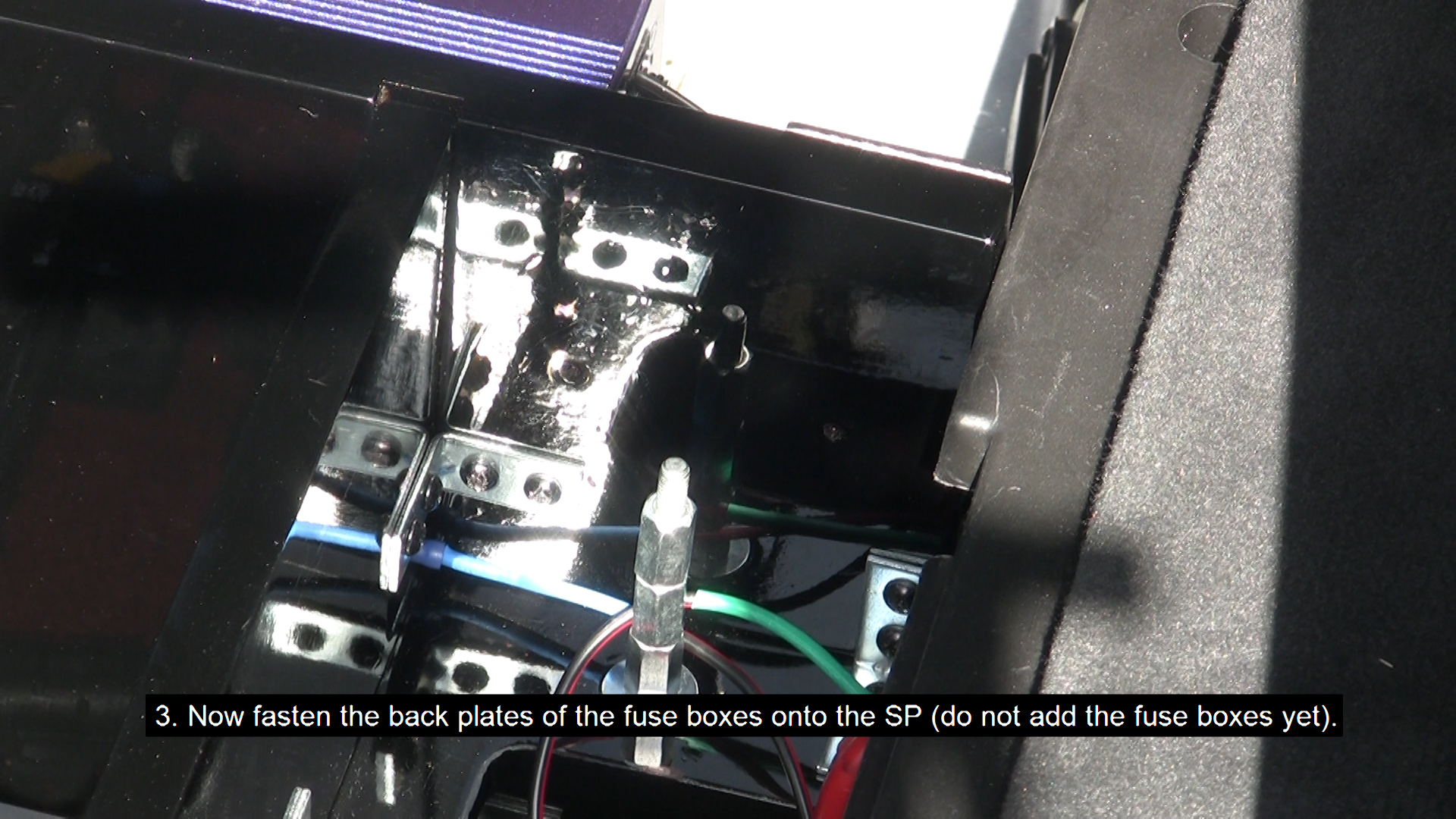
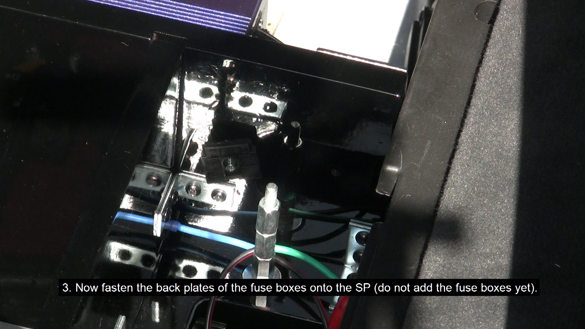
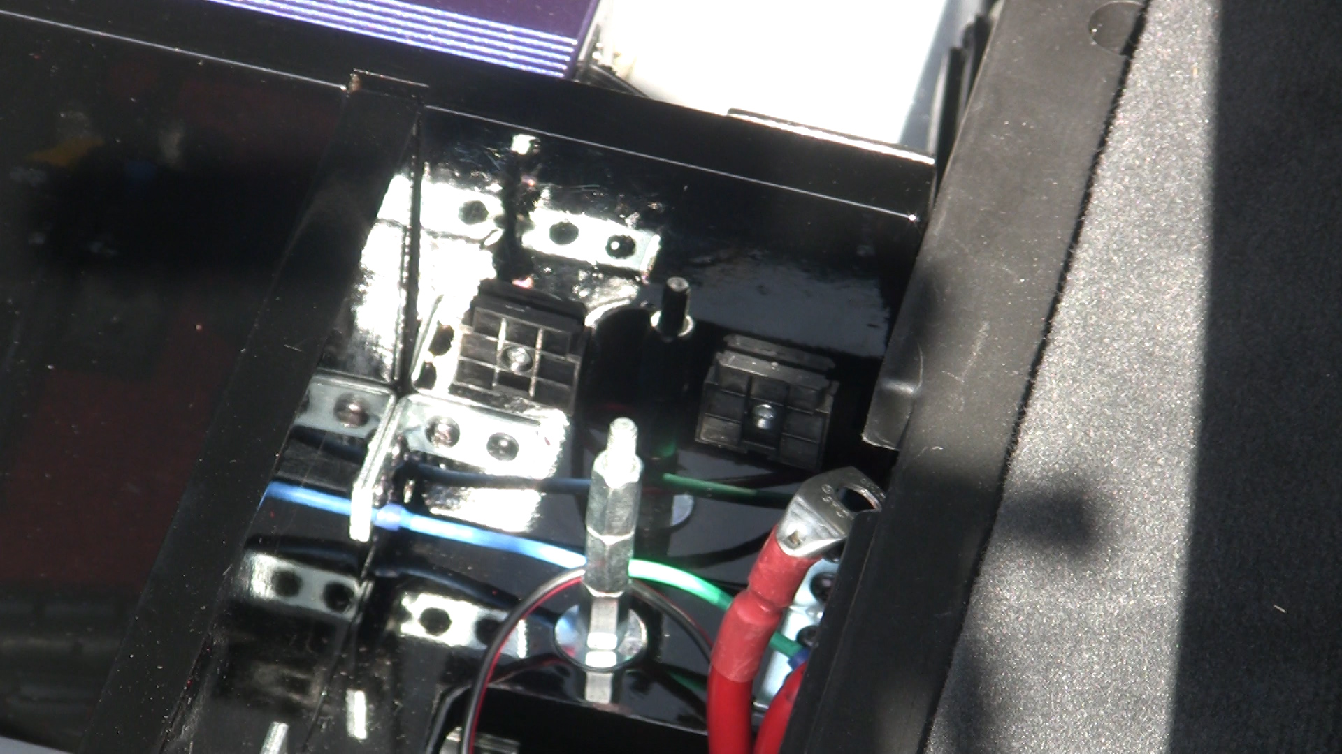
- Now fasten the back plates of the fuse boxes onto the SP (do not add the fuse boxes yet).
- Pass the thick black Inverter -ve cable (INV/N-SBB/N) through the rear opening of the Power Distribution Vertical Panel.
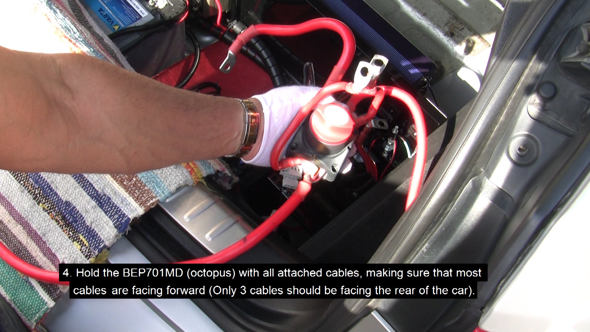
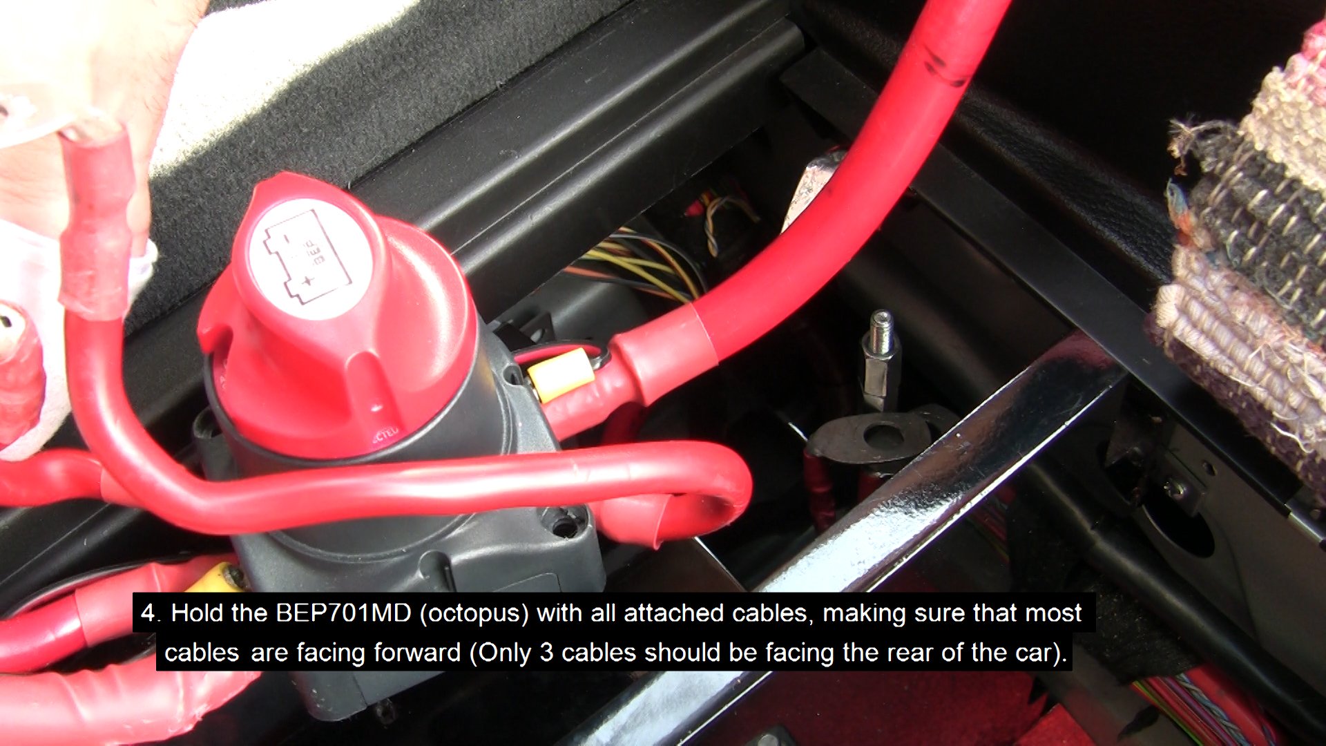
- Hold the BEP701MD (octopus) with all attached cables, making sure that most cables are facing forward (Only 3 cables should be facing the rear of the car).
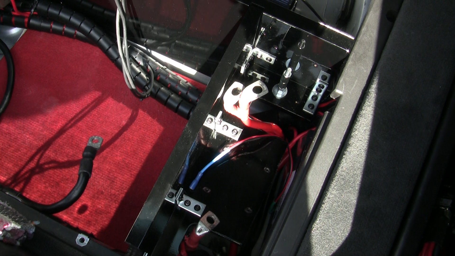
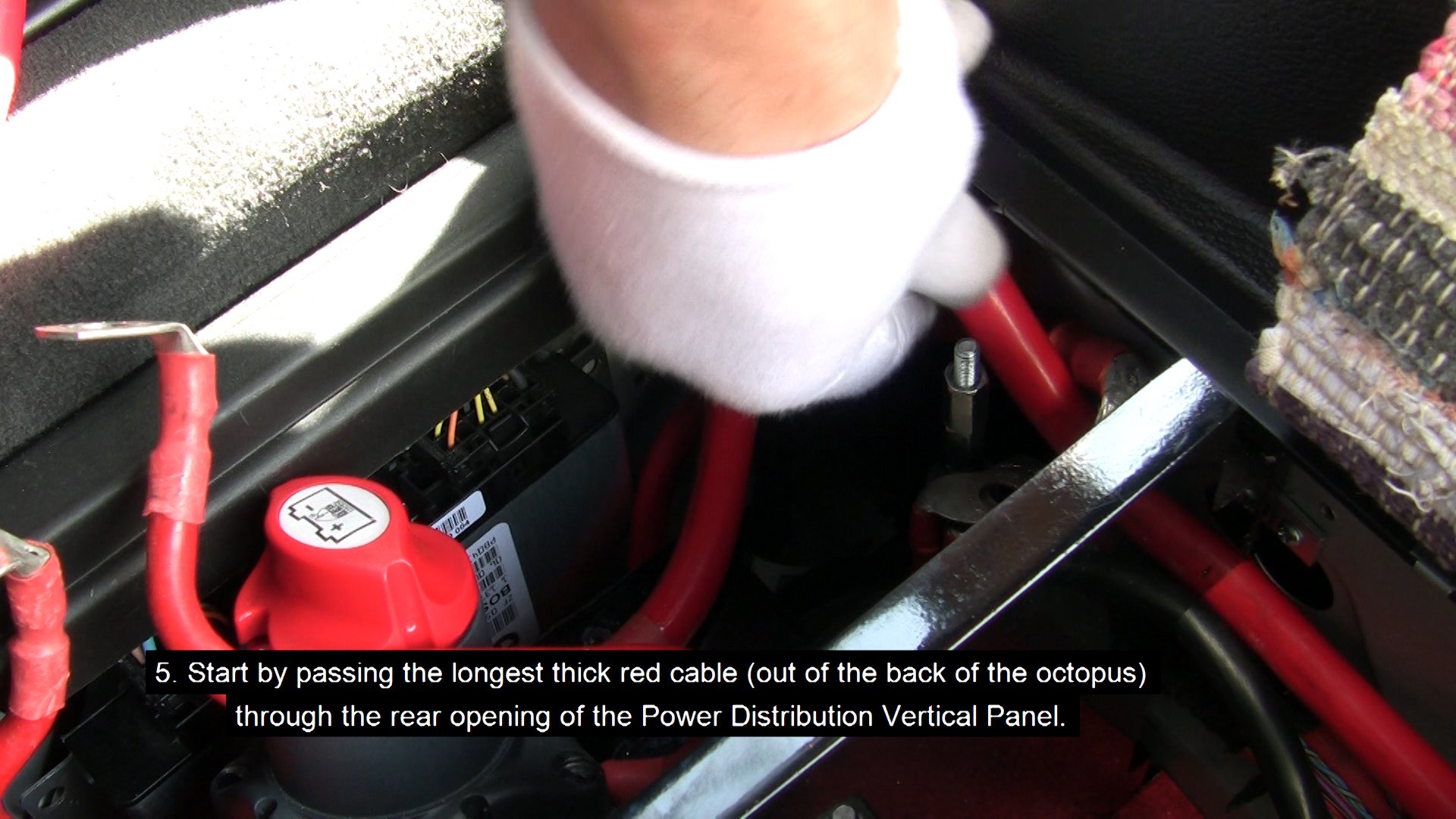
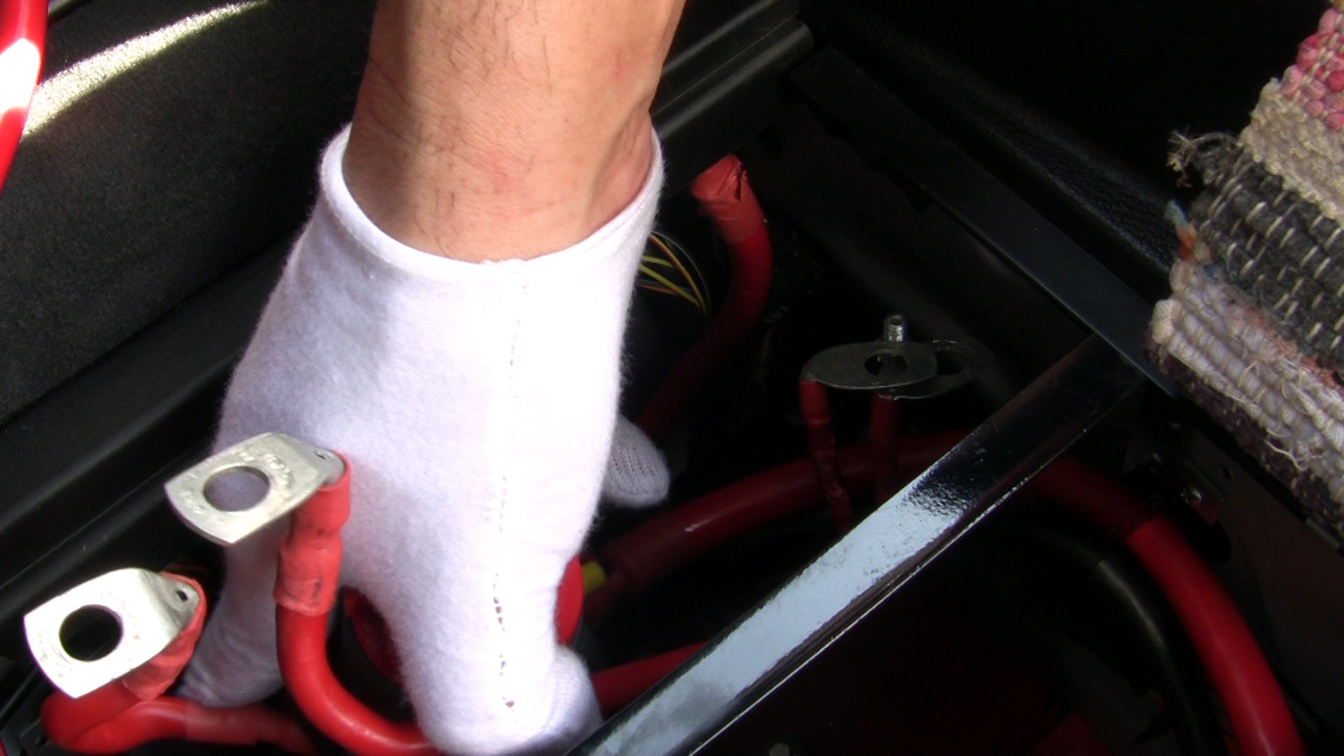
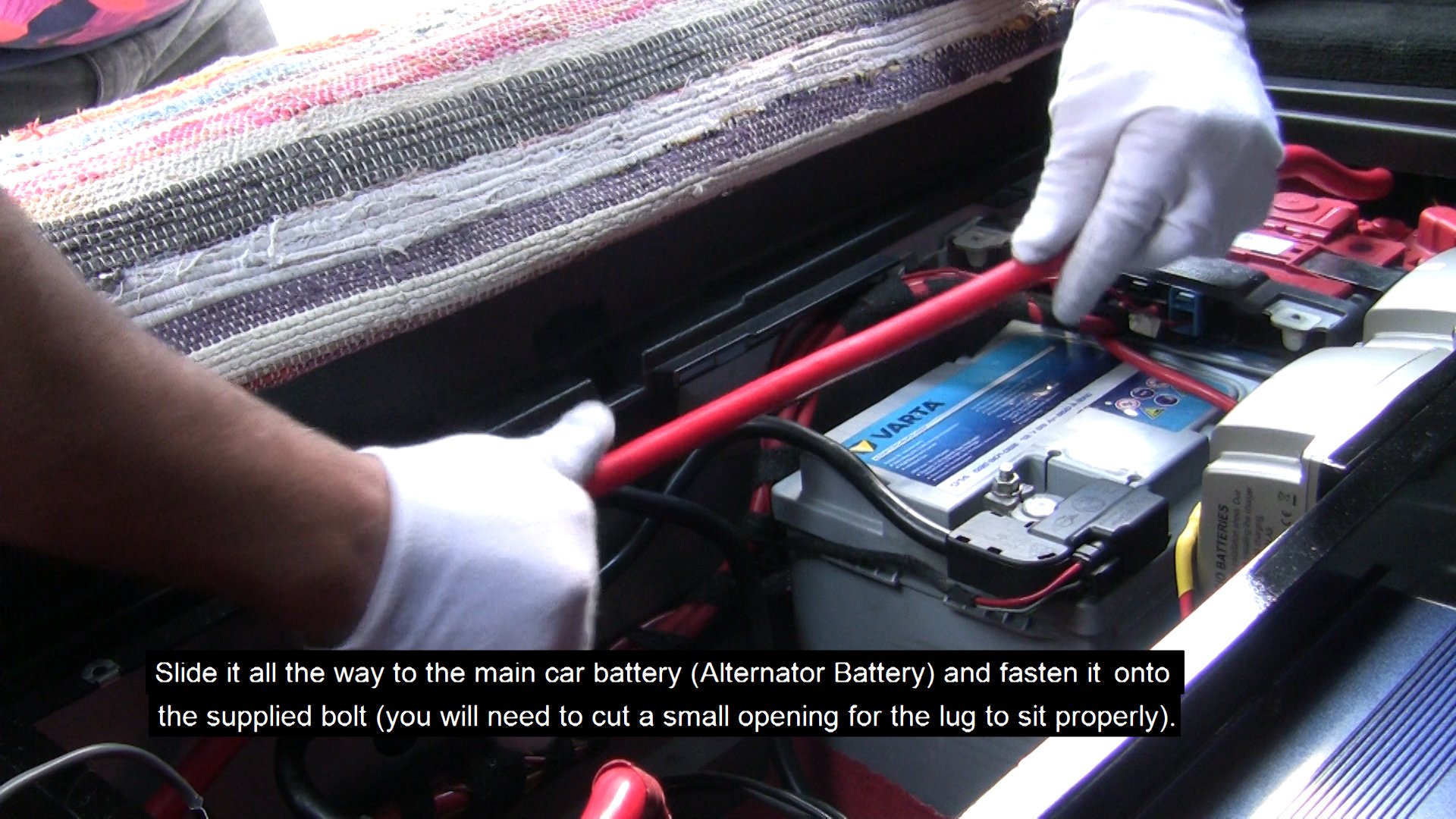
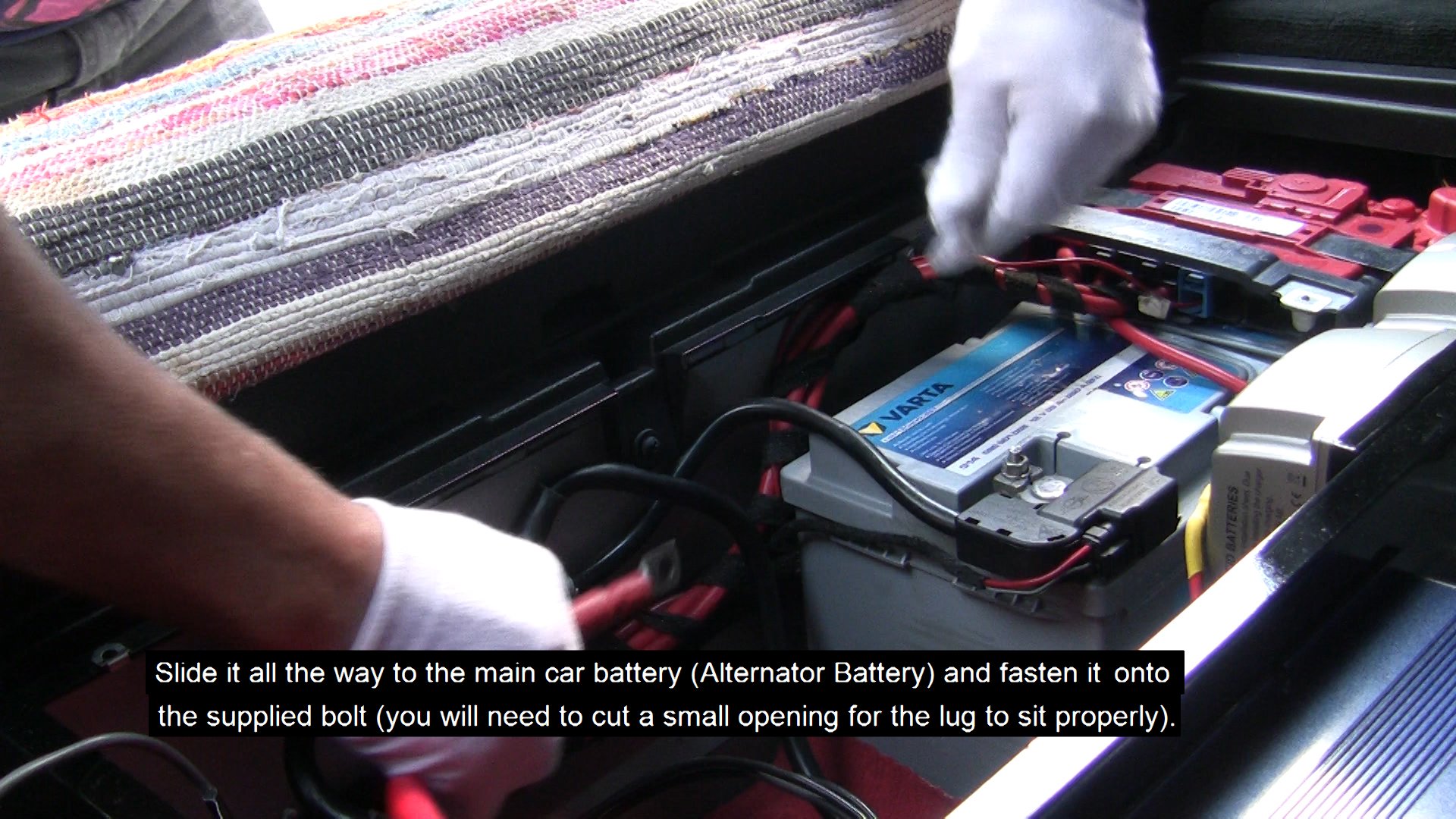
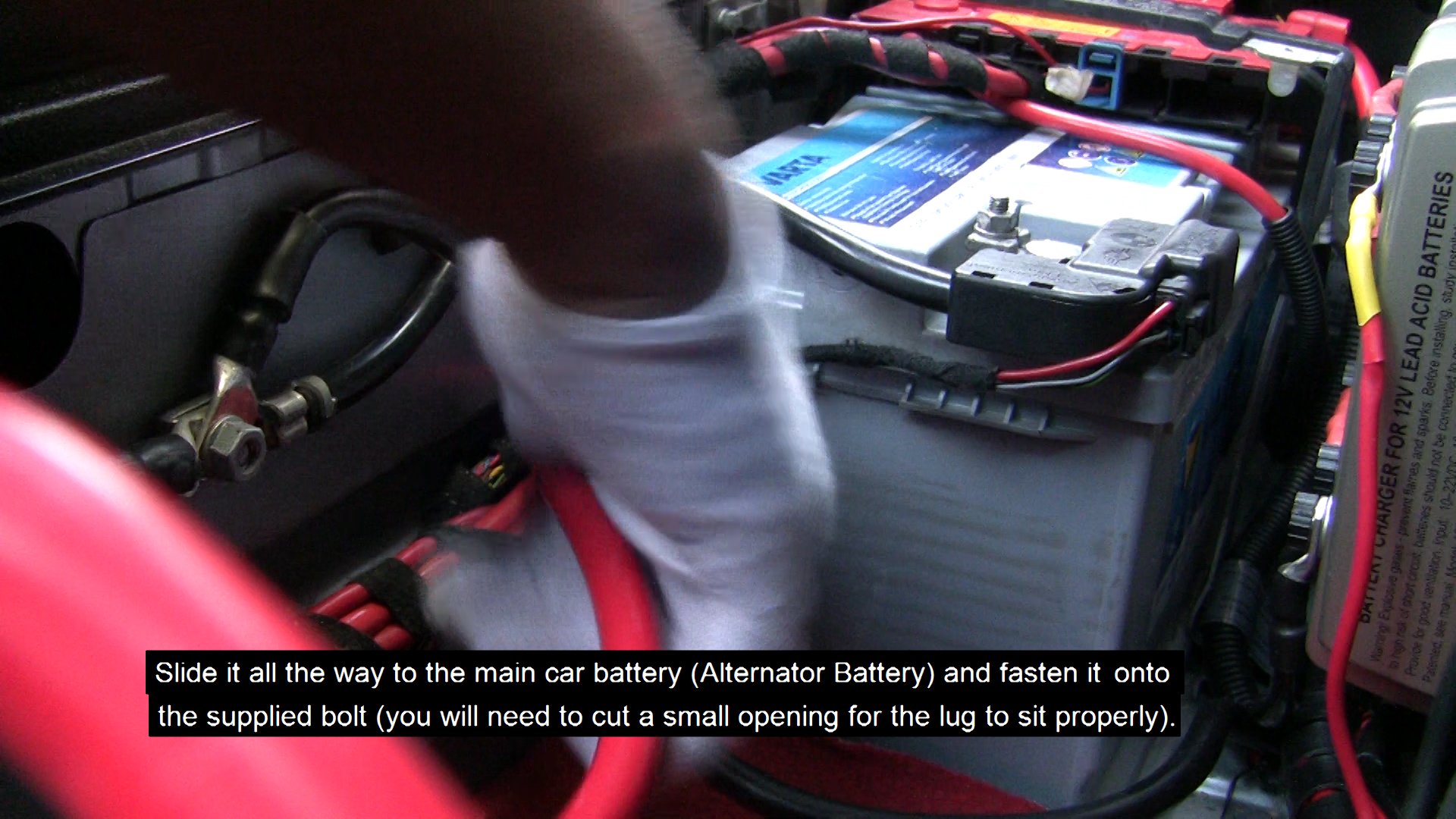
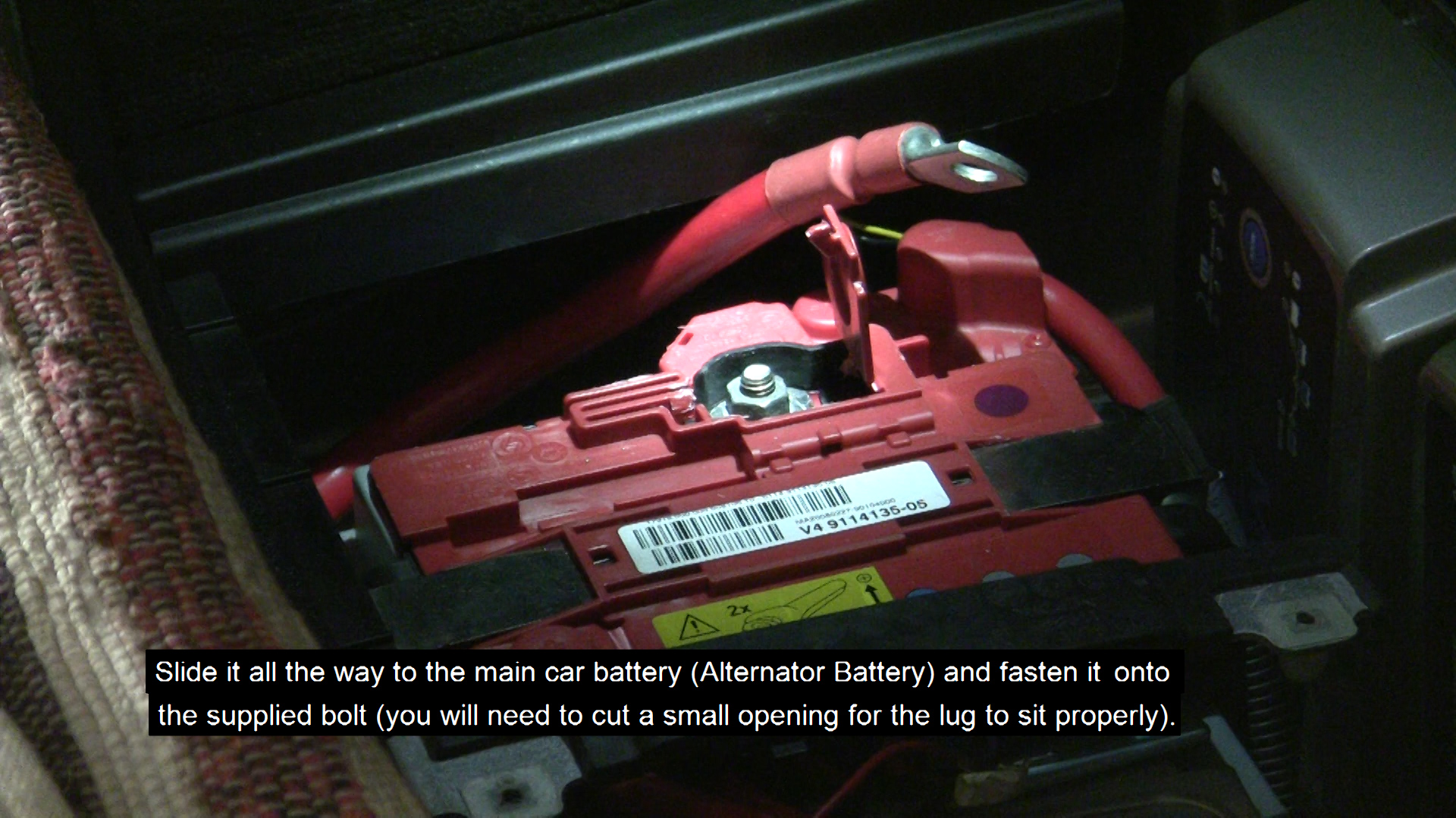
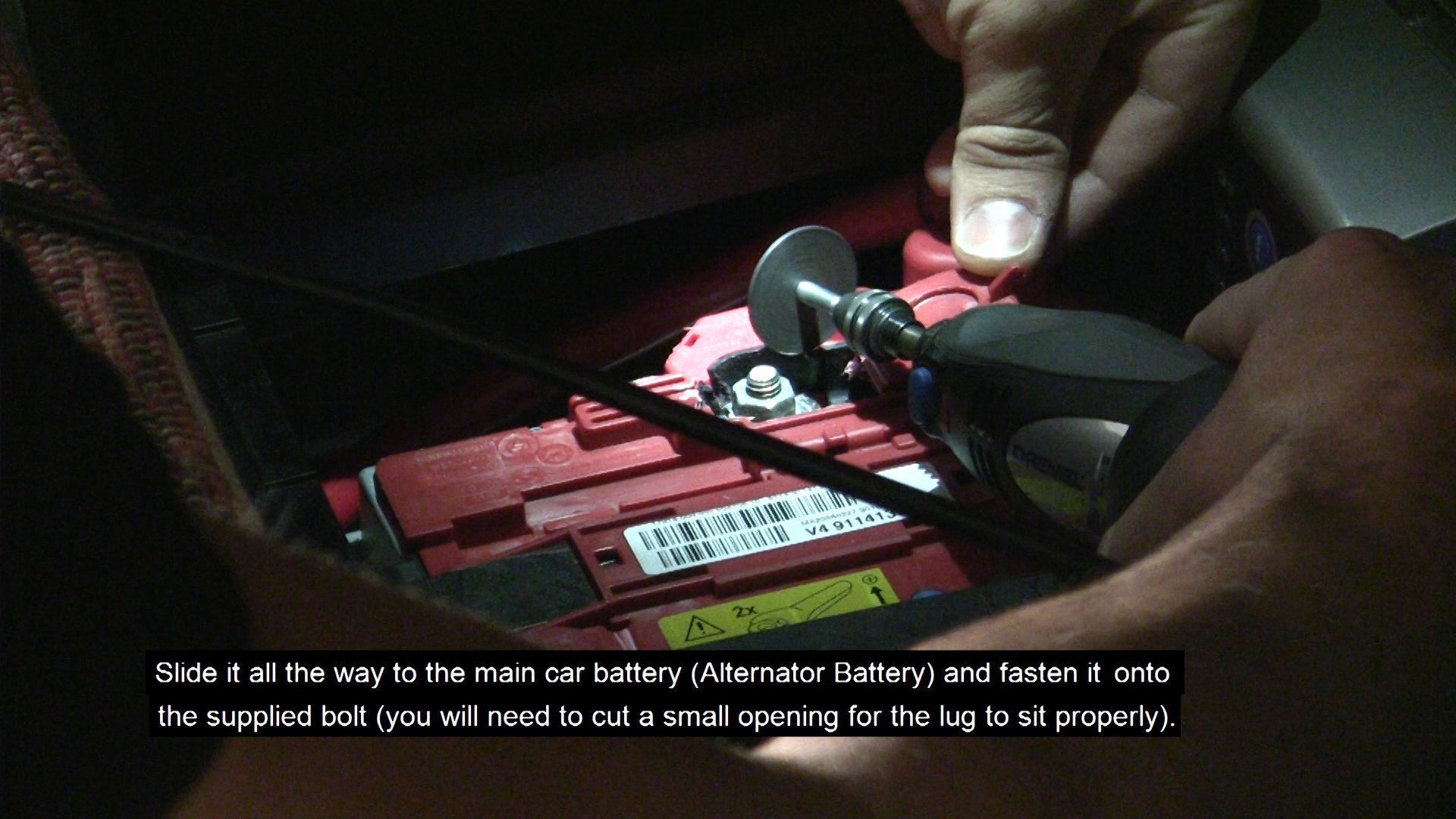
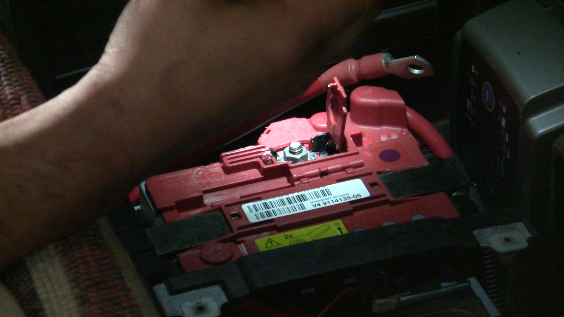
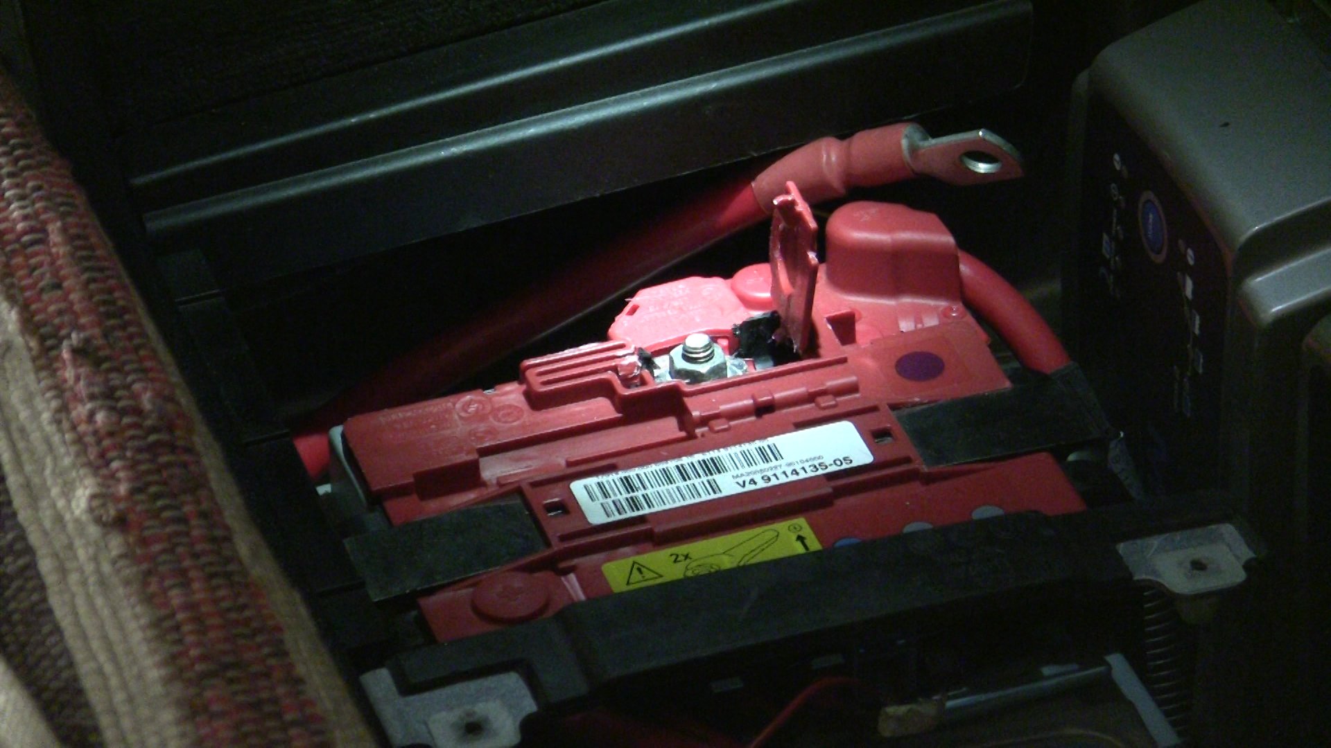
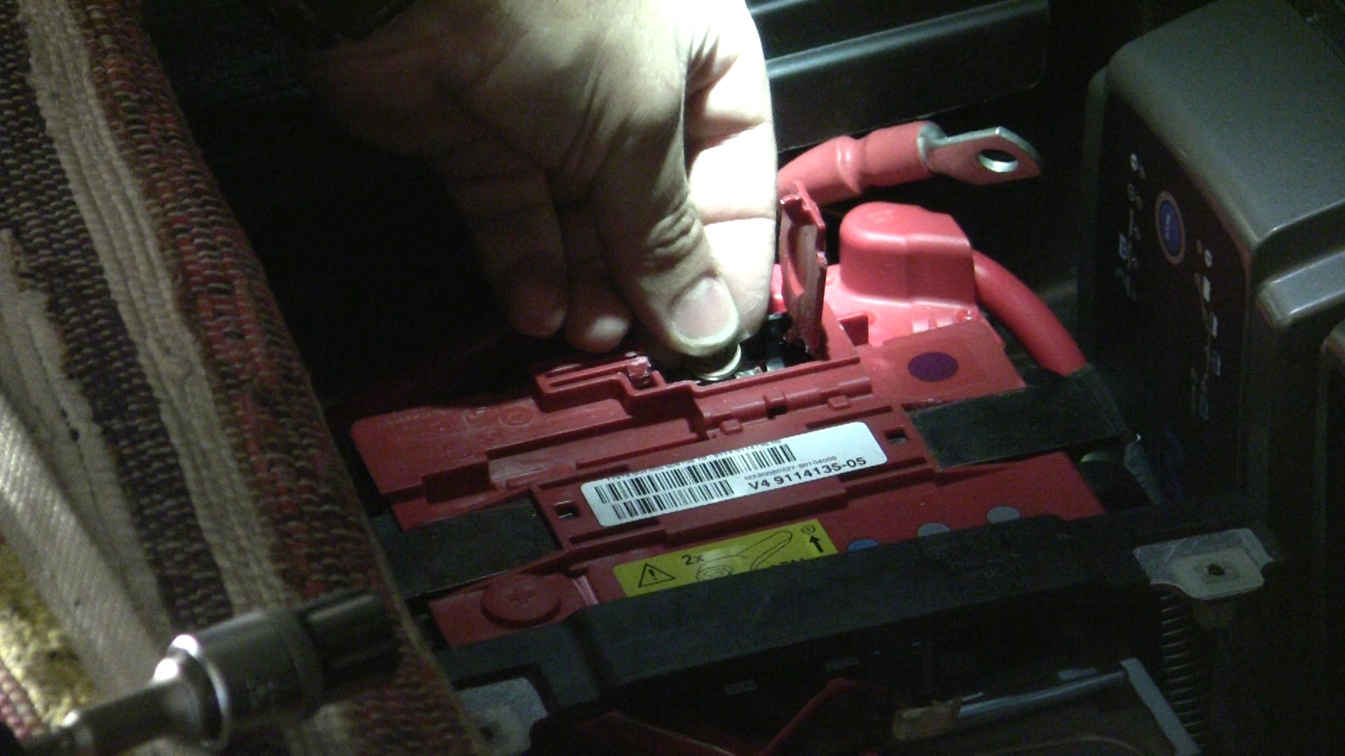
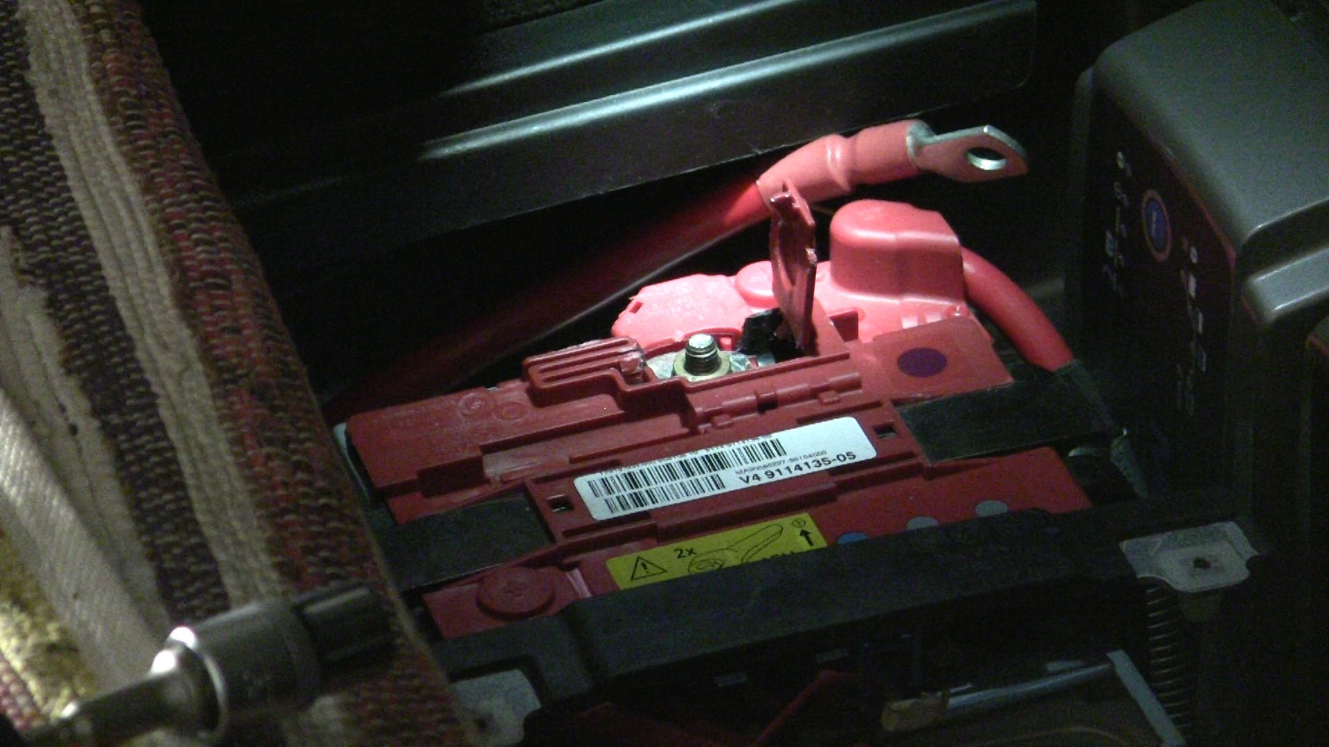
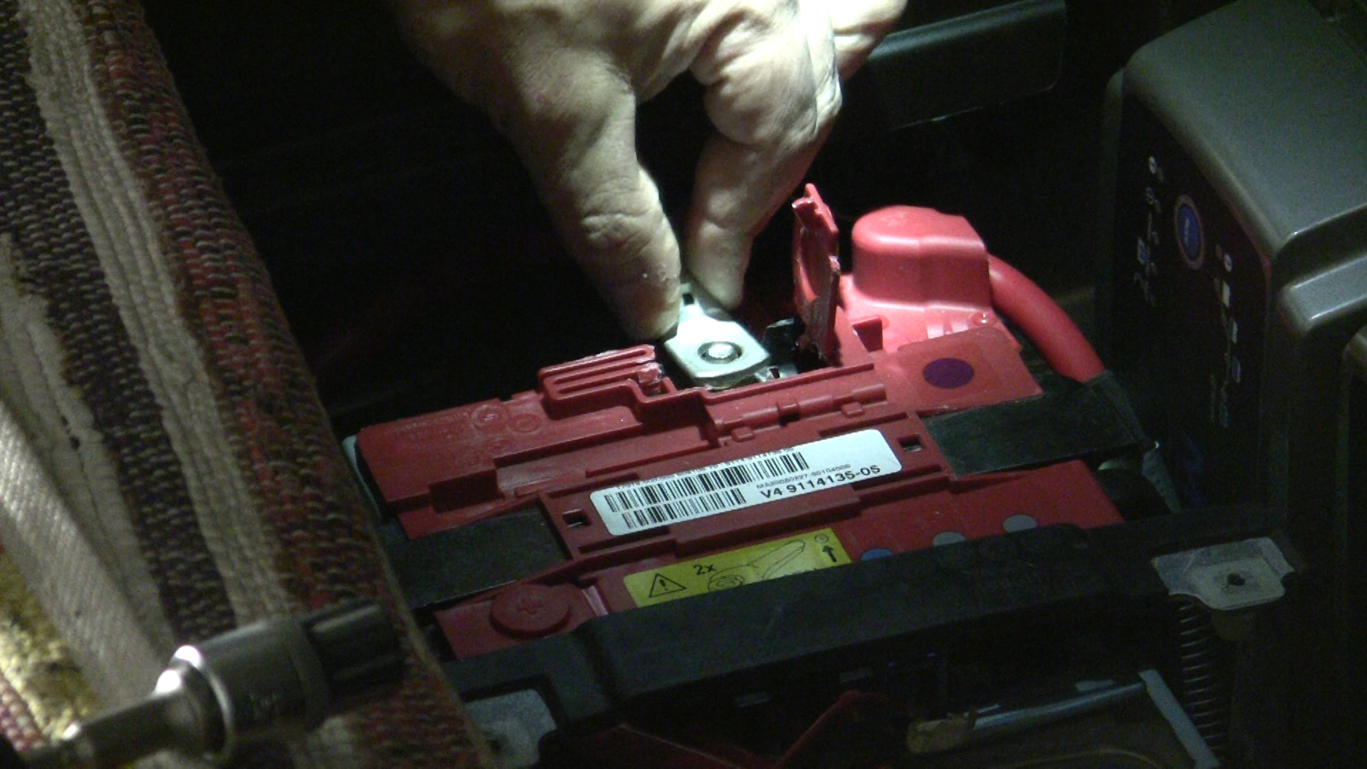
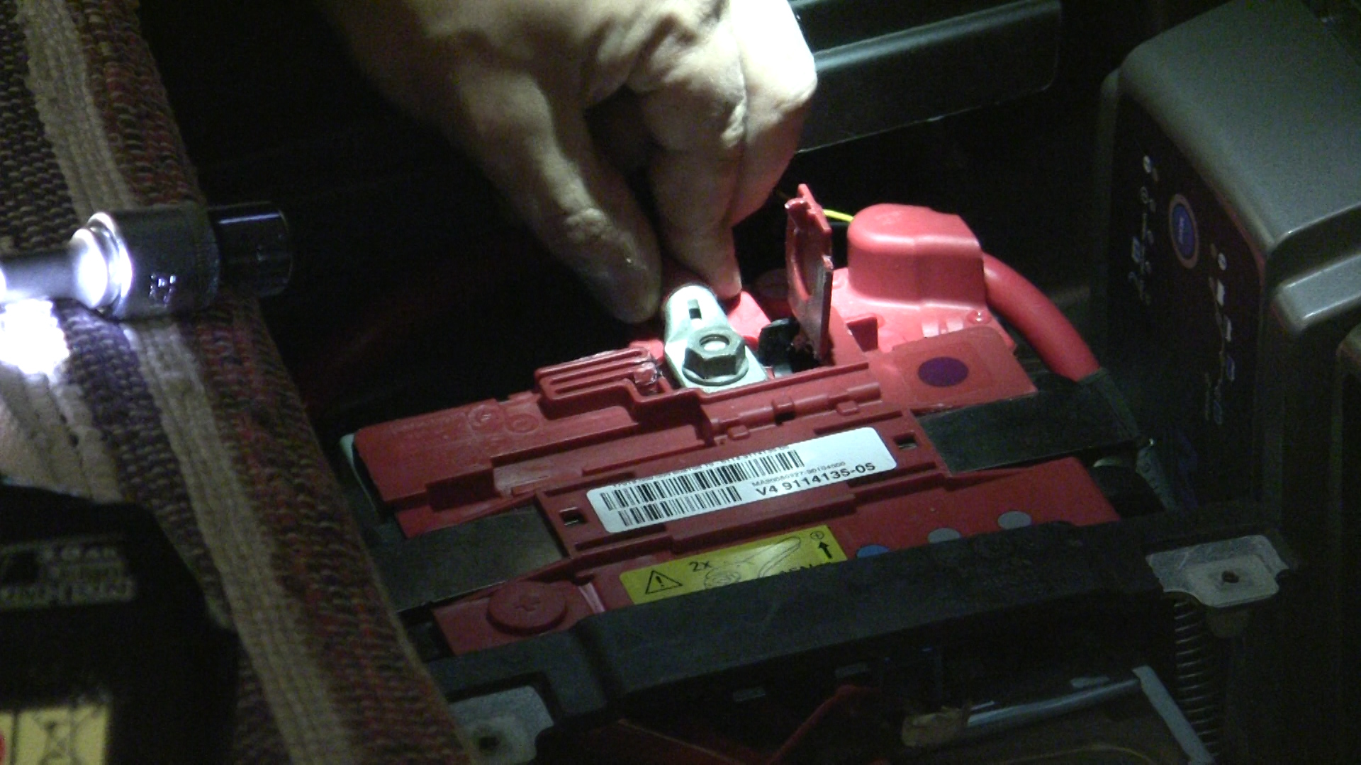
- Start by passing the longest thick red cable (blue colour-coded - BEP/AB-AB coming out of the back of the octopus) through the rear opening of the Power Distribution Vertical Panel. Slide it all the way to the main car battery (Alternator Battery) and fasten it onto the supplied bolt (you will need to cut a small opening on the plastic cover and a couple of washers for the lug to sit properly).
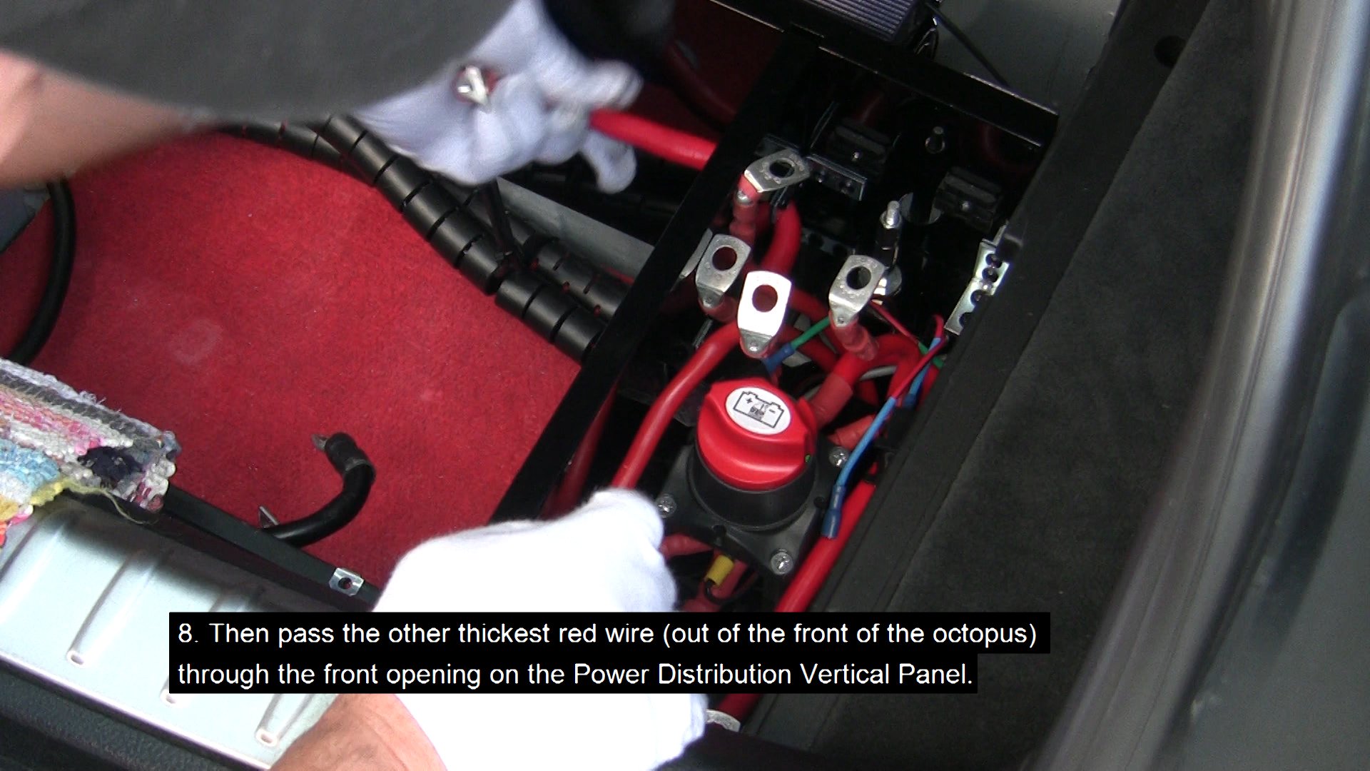
- Then pass the other thickest red wire (red colour-coded - BEP/SBB-SBB coming out of the front of the octopus) through the front opening on the Power Distribution Vertical Panel.
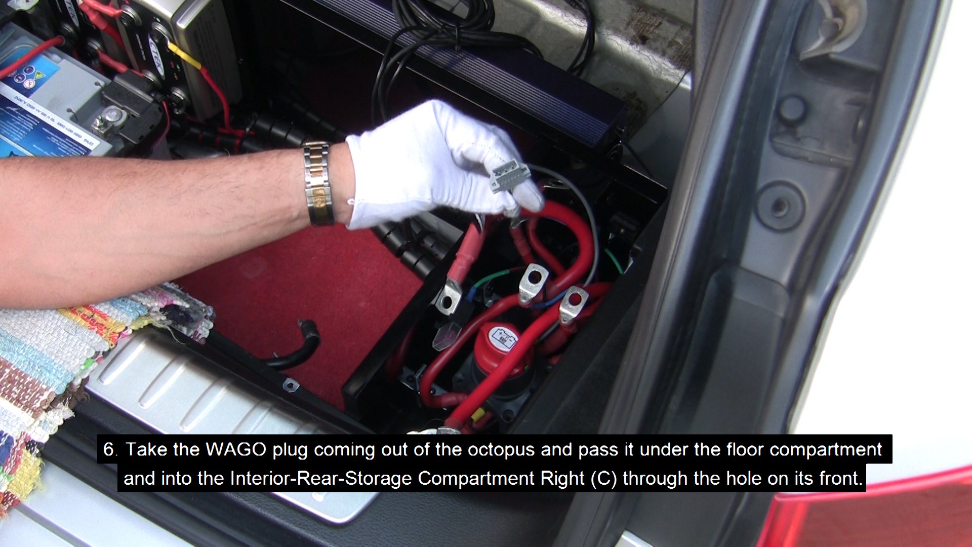
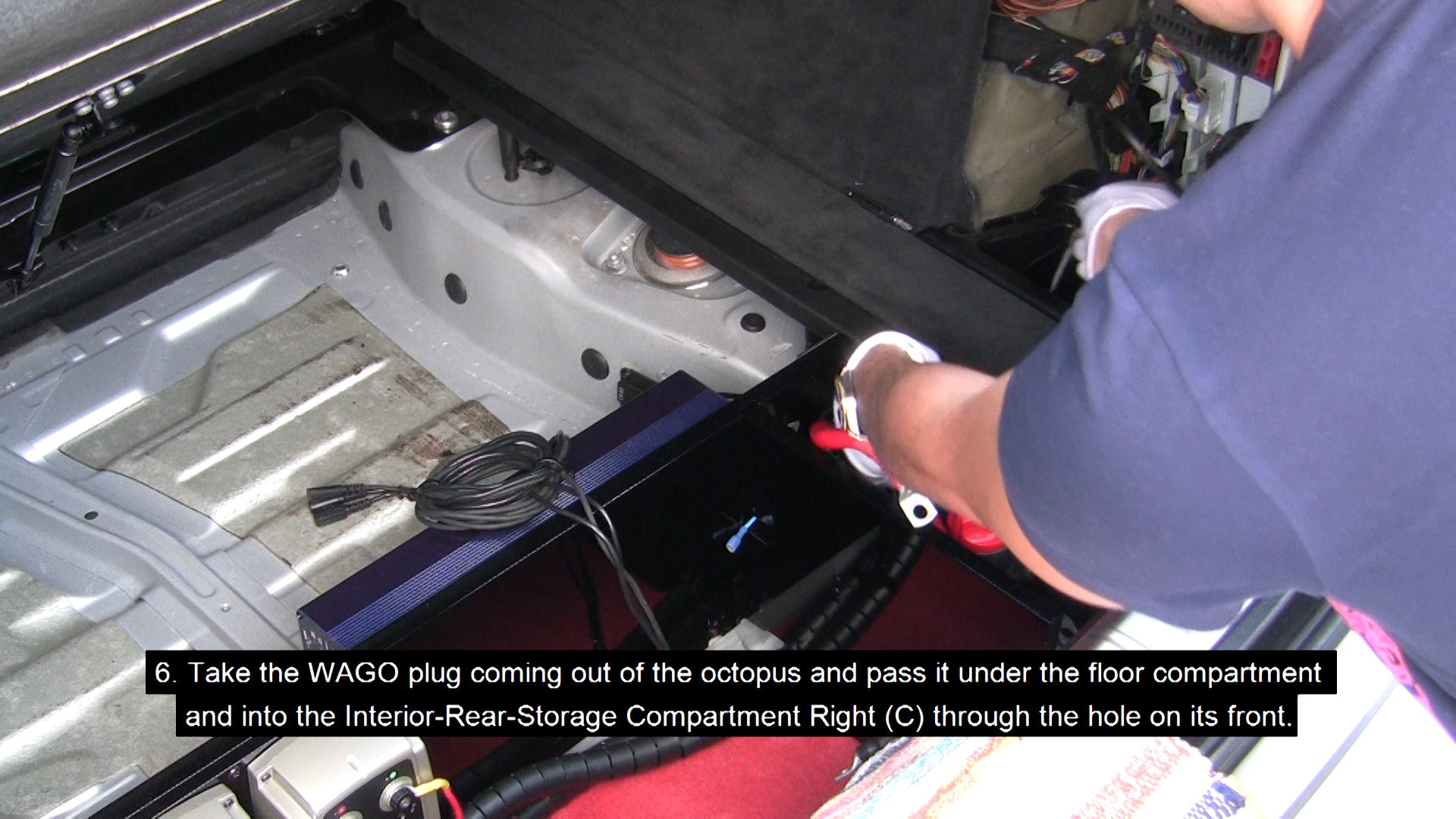
- Take the WAGO plug coming out of the octopus and pass it under the floor compartment and into the Interior-Rear-Storage Compartment Right (C) through the hole on its front.
- Now you can fasten the BEP701 onto the Power Distribution Bottom Panel.
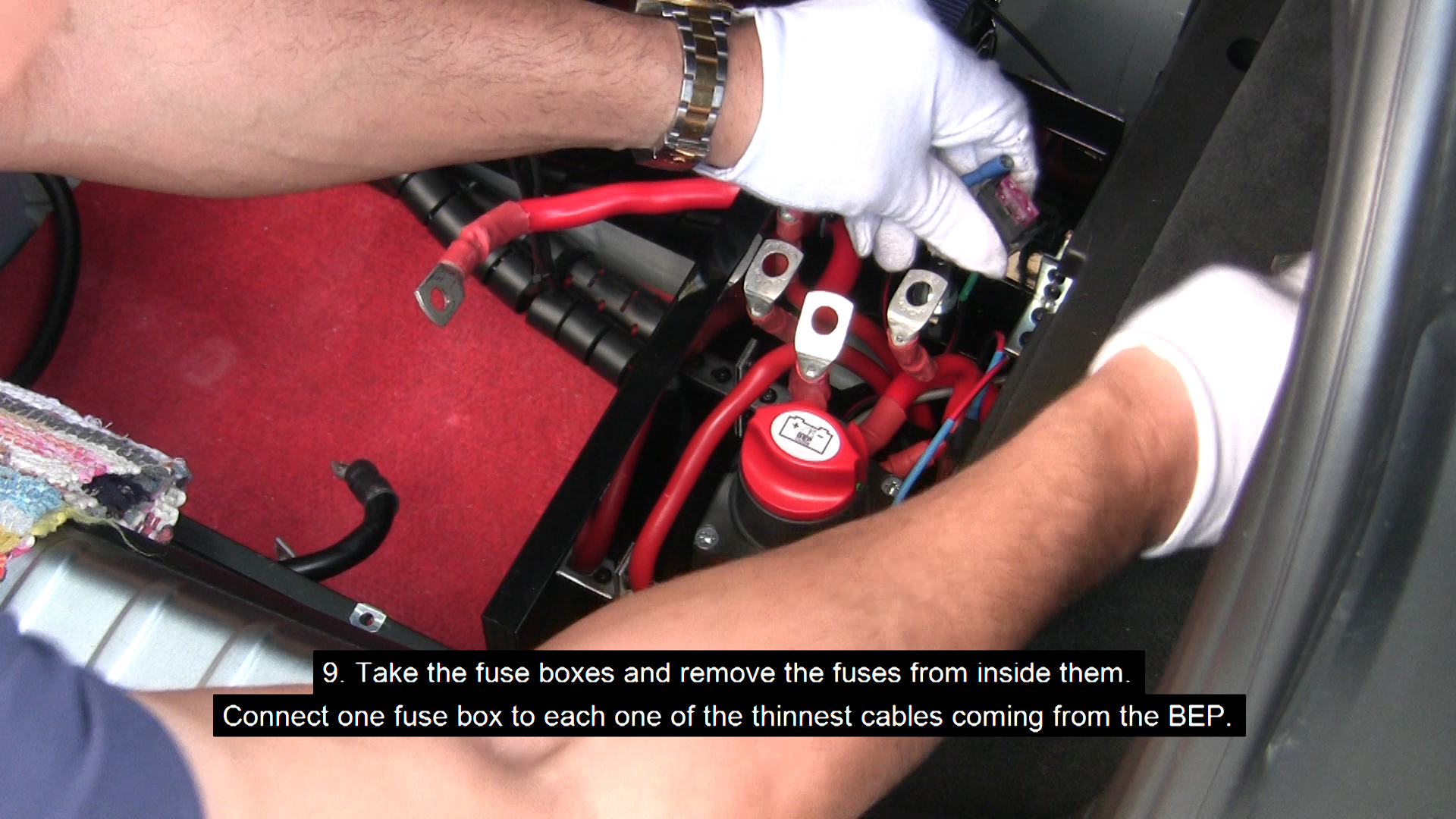
- Take the fuse boxes and remove the fuses from inside them. Connect one fuse box to each one of the thinnest cables coming from the BEP. Connect the remaining empty slot of each fuse box with the thinnest cables on LOOM1, making sure the colours match for both cables connected to each fuse box (the order of the cables on each fuse box does not matter).
- Place the fuse box with the blue colour-coded cables (AB) and slot it in place on the left-most slot, while the other one with the red colour-coded cables (SBB) should be slotted on the right hand slot.
Please note: It really makes no difference where you slot the fuse boxes, but let's keep AB on the left and SBB on the right to keep things organized.
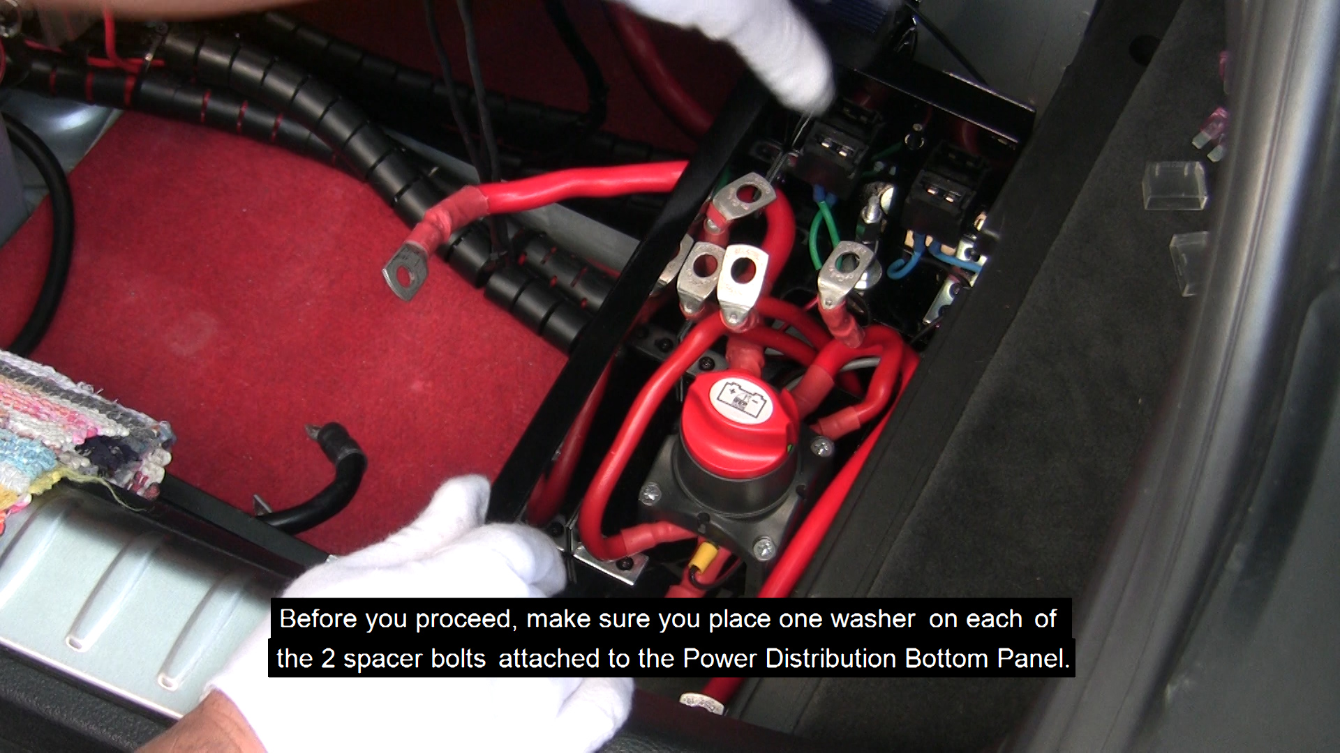
- Now, place one washer on each of the 2 spacer bolts attached to the Power Distribution Bottom Panel.
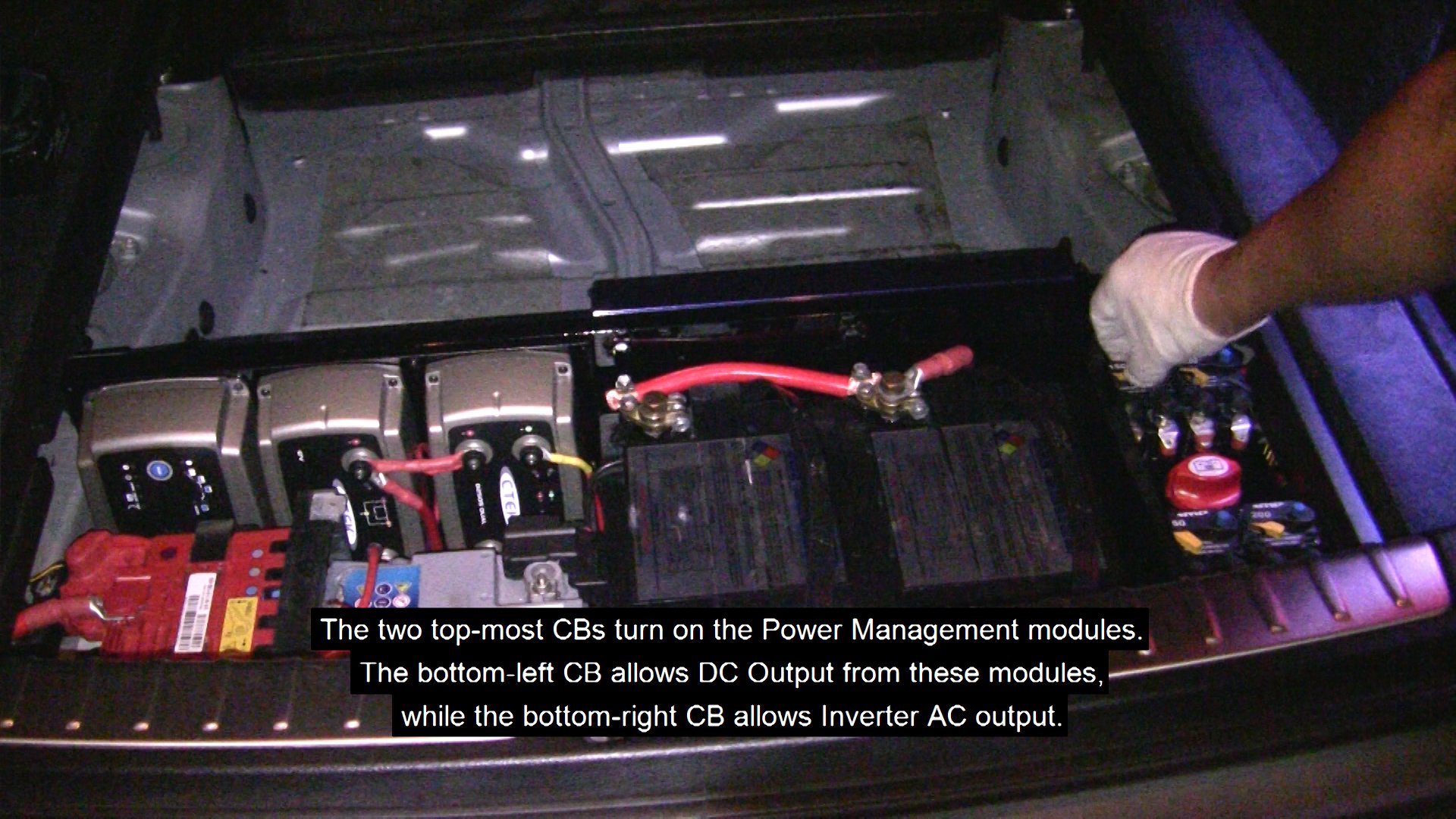
How to pair the cables for each CB:
There are a total of 8 cables that need to be matched. They are colour-coded so this should be pretty easy.
The 2 thinnest cables go to the bottom left slots (DC out cables - CB#6 - White) while the 2 thickest cables go to the bottom right slots (Inverter cables - CB#7 - Green).
All other cables go to the topmost slots (AB – CB#4 - Blue - Left, SBB – CB#5 - Red - Right).
Each circuit breaker has an indication on each pole – AUX (left) & BAT (right), (translated as OUT & IN respectively).
Also half of the cables have a black dot indication mark on their lugs to indicate an IN cable.
IN cables should always be placed in the right-most slots of each pair of slots.
- Take the Power Distribution Top Panel and start passing each of the 8 remaining cables through the holes provided.
Place the white colour-coded cables in the bottom-left pair of slots (CB#6), making sure the IN cable is placed in the right-most position of this slot.
IN cable coming from the Smartpass. OUT cable going to the SCP.
- Place the green colour-coded cable (coming out of the front of the octopus) to the right-most slot of the bottom-right pair of slots (CB#7). Place the other green colour-coded cable in the adjacent position of this slot.
IN cable coming from the front of the octopus. OUT cable going to the Inverter.
- Place the blue colour-coded cable (coming out of the rear of the octopus) to the right-most position of the top-left pair of slots (CB#4). Fill the adjacent slot with the matching colour-coded cable.
IN cable coming from the back of the octopus. OUT cable going to the Smartpass.
- Place the red colour-coded cable (coming out of the front of the octopus) to the right-most position of the top-right pair of slots (CB#5). Fill the adjacent slot with the matching colour-coded cable.
IN cable coming from the back of the octopus. OUT cable going to the Smartpass.
- When all cables have been slotted in, carefully lower the Power Distribution Top Panel into position. No force is required here. Just make sure you clear the 2 fuseboxes which should be perfectly straight if the panel is going to sit properly. Start lowering the panel backside-first to clear any obstruction from the rear trunk wall.
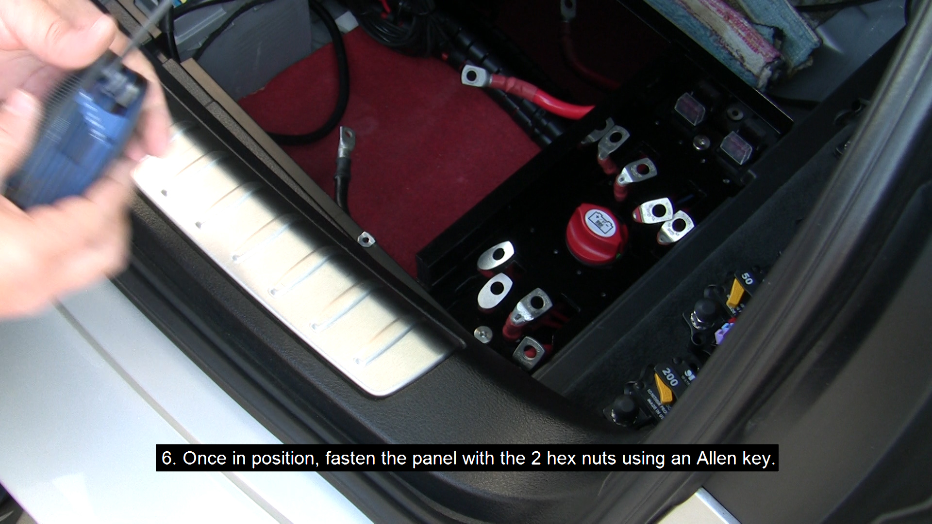
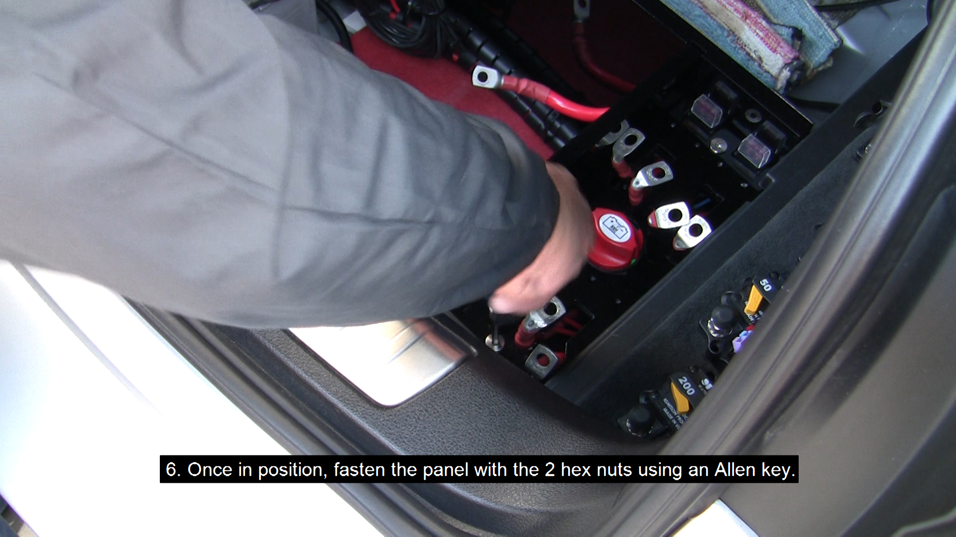
- Once in position, fasten the panel with the 2 hex nuts using an Allen key.
Please note: you may need to use a thin screwdriver to position the bolt in the middle of the hole where the hex nut is going to sit so that it can catch onto it.
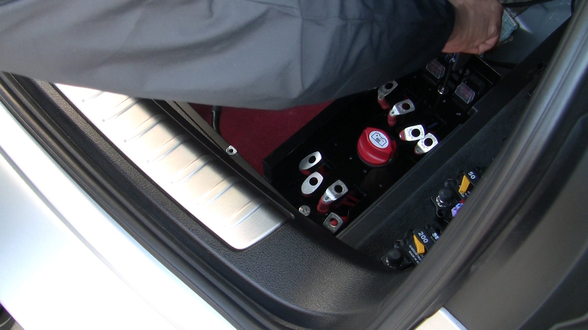
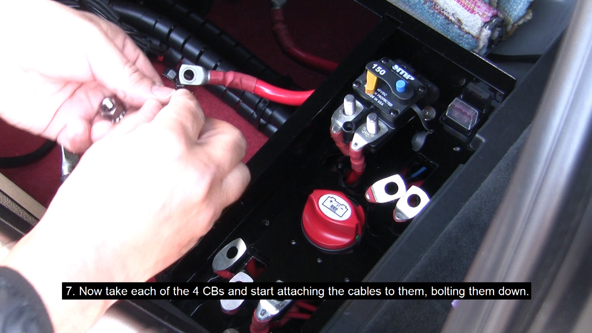
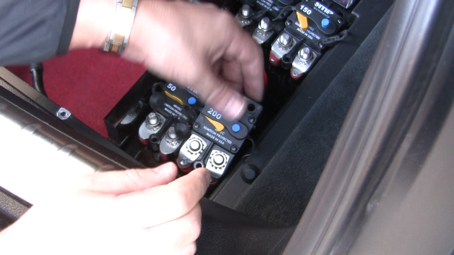
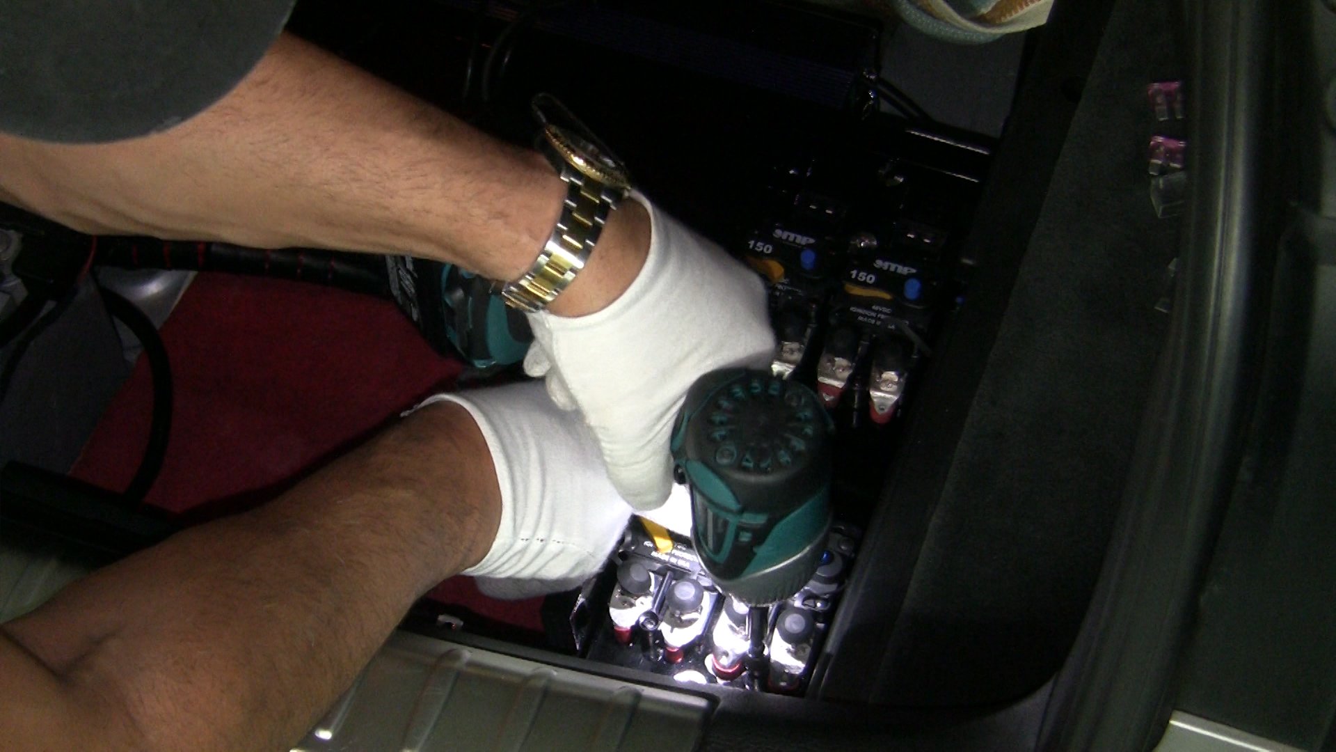
- Now take each of the 4 CBs and start attaching the cables to them, bolting them down.
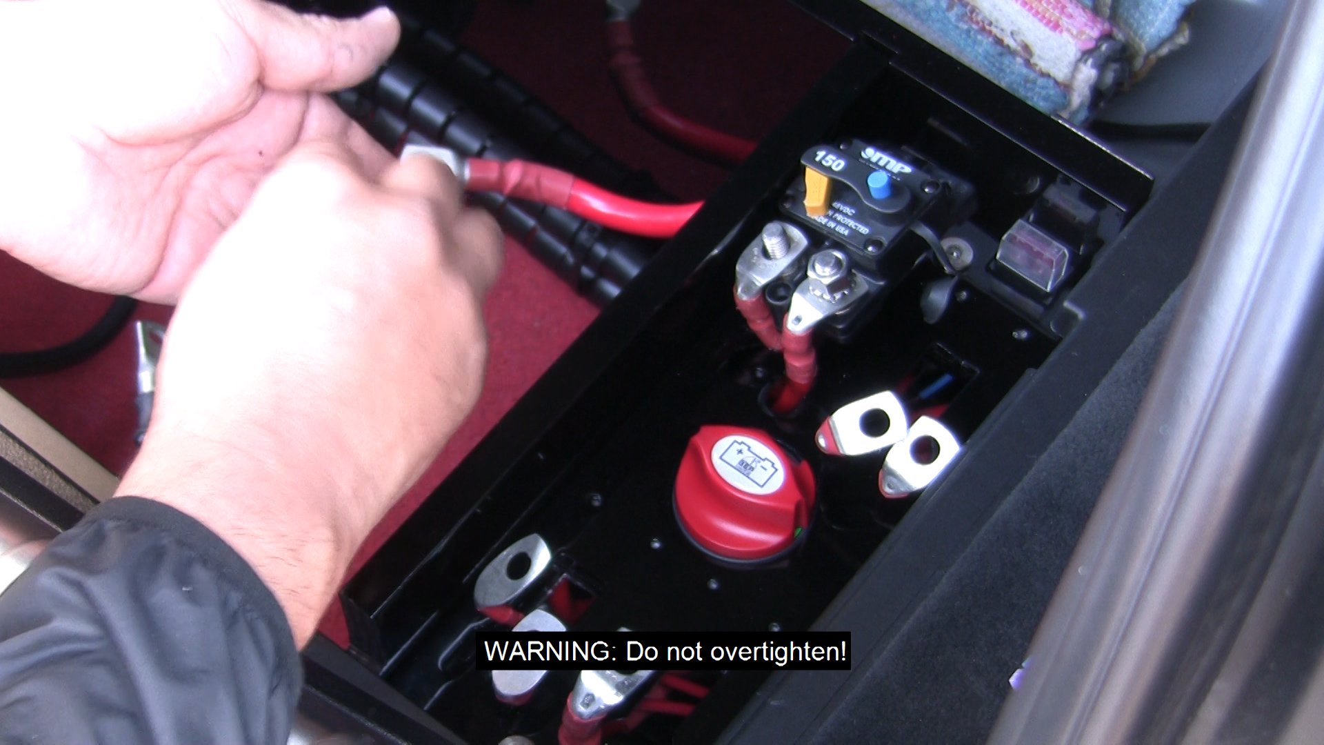
WARNING: Do not overtighten!
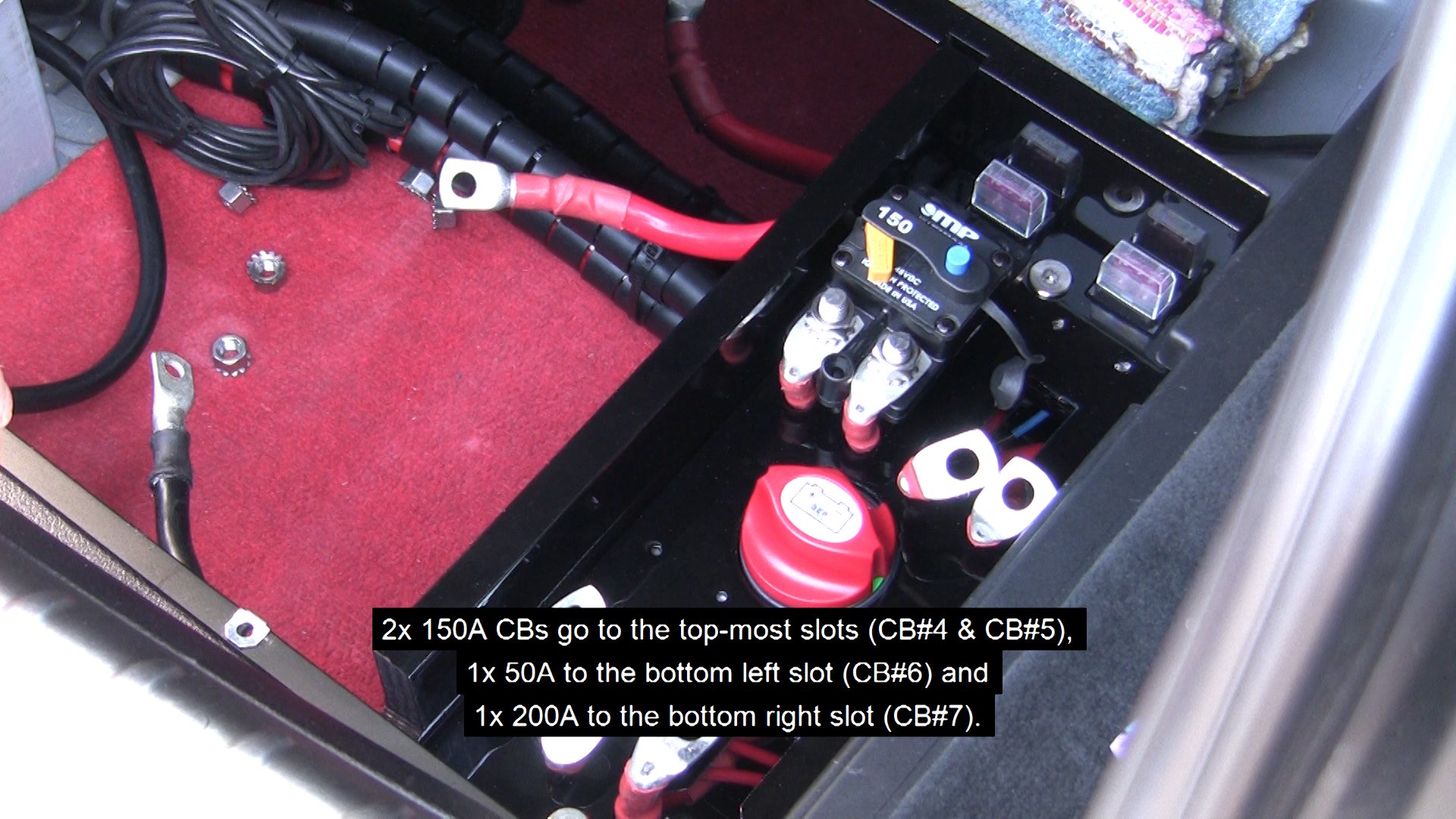
2x 150A CBs go to the top-most slots (CB#4 & CB#5), 1x 50A to the bottom left slot (CB#6) and 1x 200A to the bottom right slot (CB#7).
You will probably need to put some pressure on the CBs in order for them to sit down properly, so please make sure that they are nearly flat on the panel before you start screwing them down.
CAUTION: make sure you attach the right CB to the right slot. Failure to do so will result in malfunction of the system or even damage.
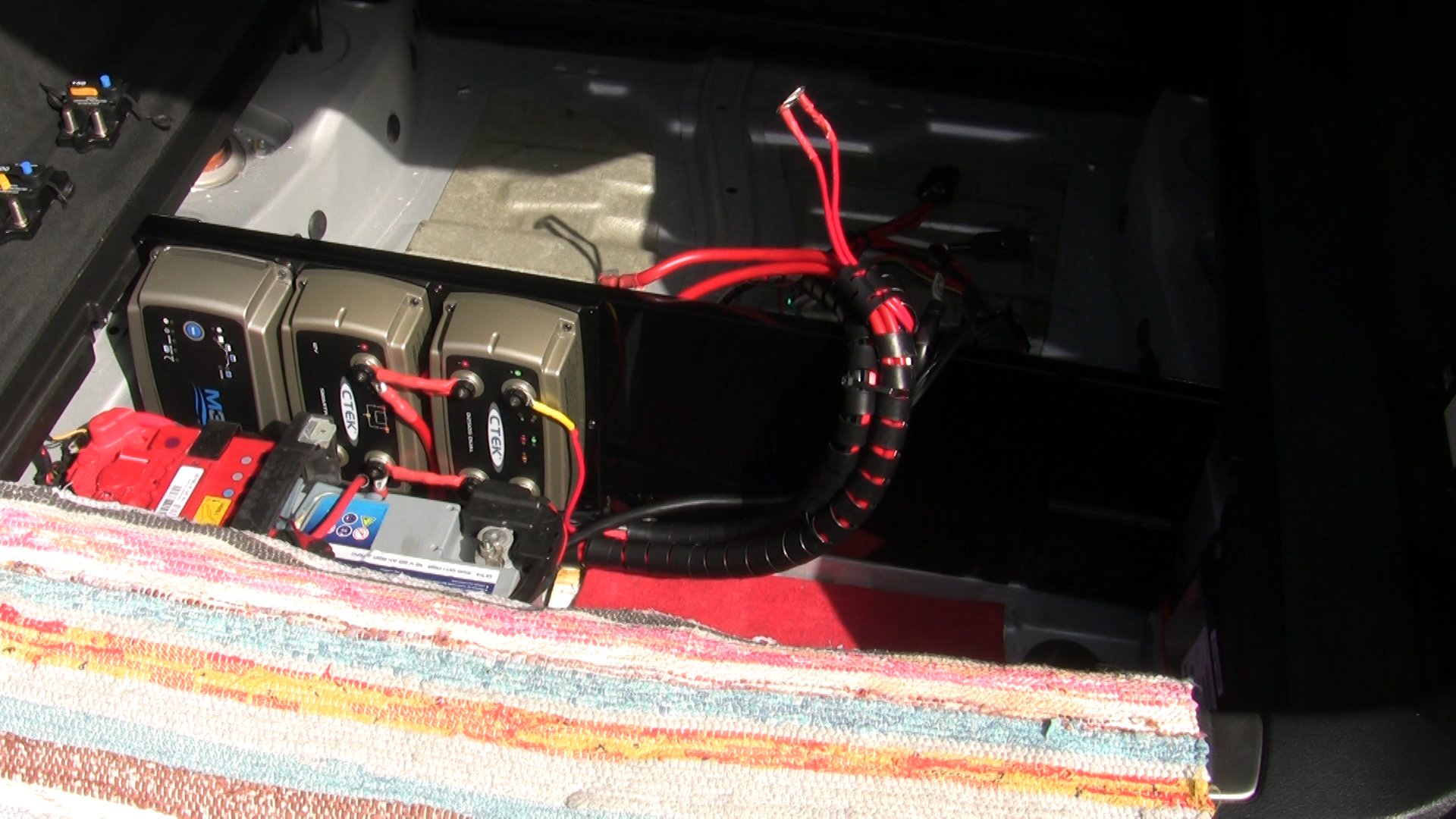
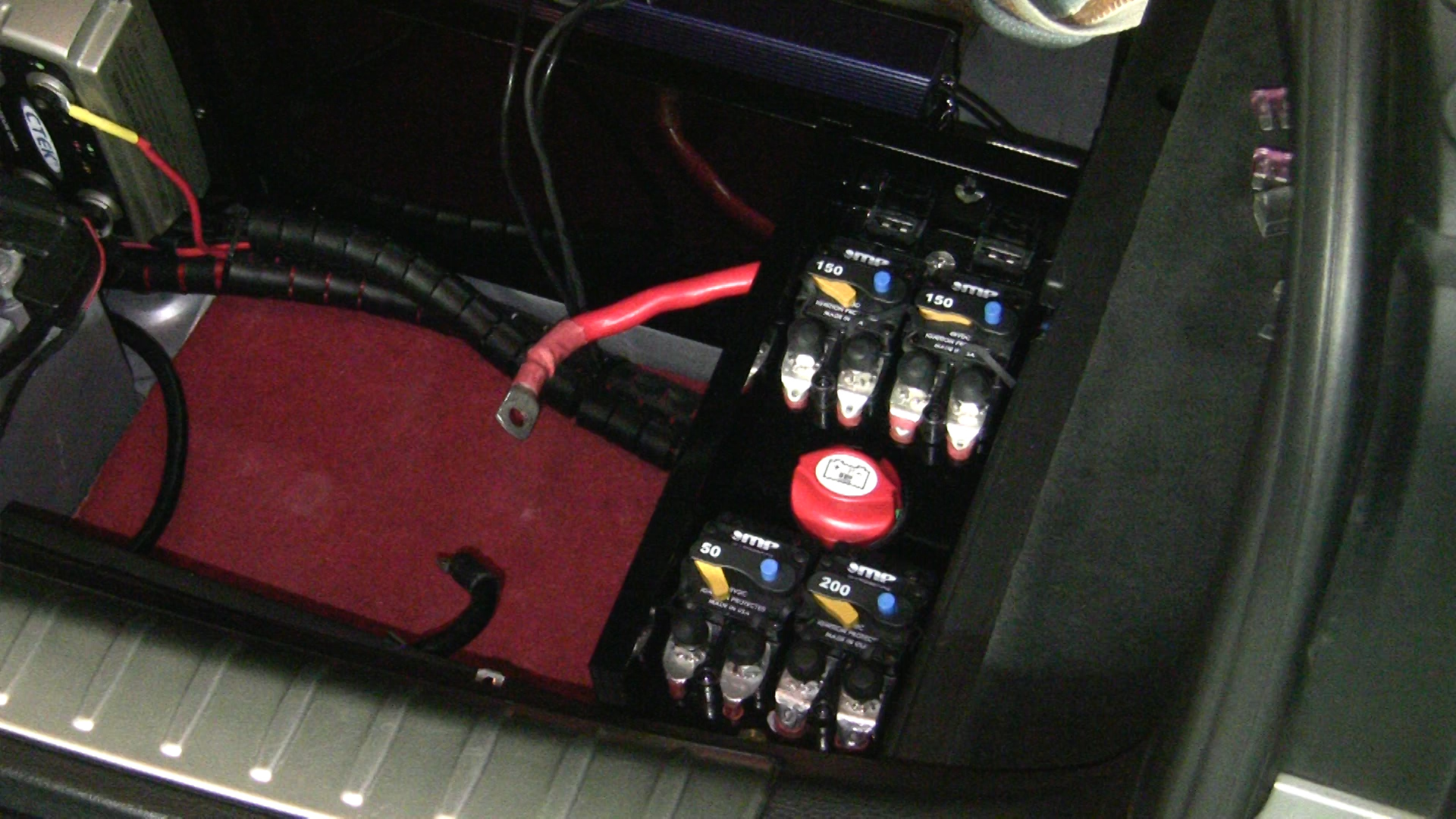
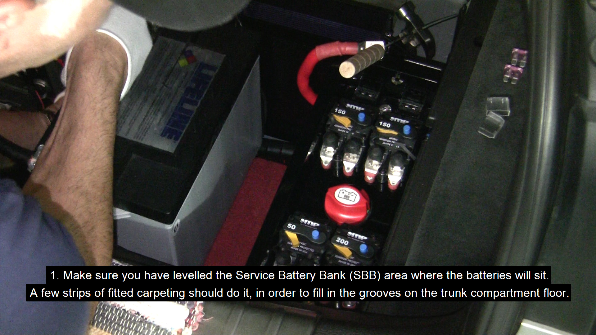
- Make sure you have levelled the Service Battery Bank (SBB) area where the batteries will sit.
Please Note: A few strips of fitted carpeting should do it, in order to fill in the grooves on the trunk compartment floor.
- Move all cables out of the way and lower the first battery. After the first battery sits flat, push it all the way towards the PD Vertical Panel and make sure it lays flat against it without any space between them.
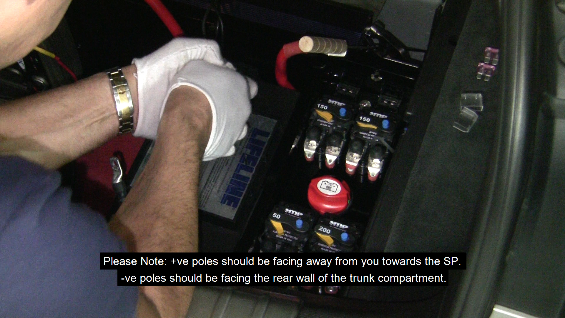
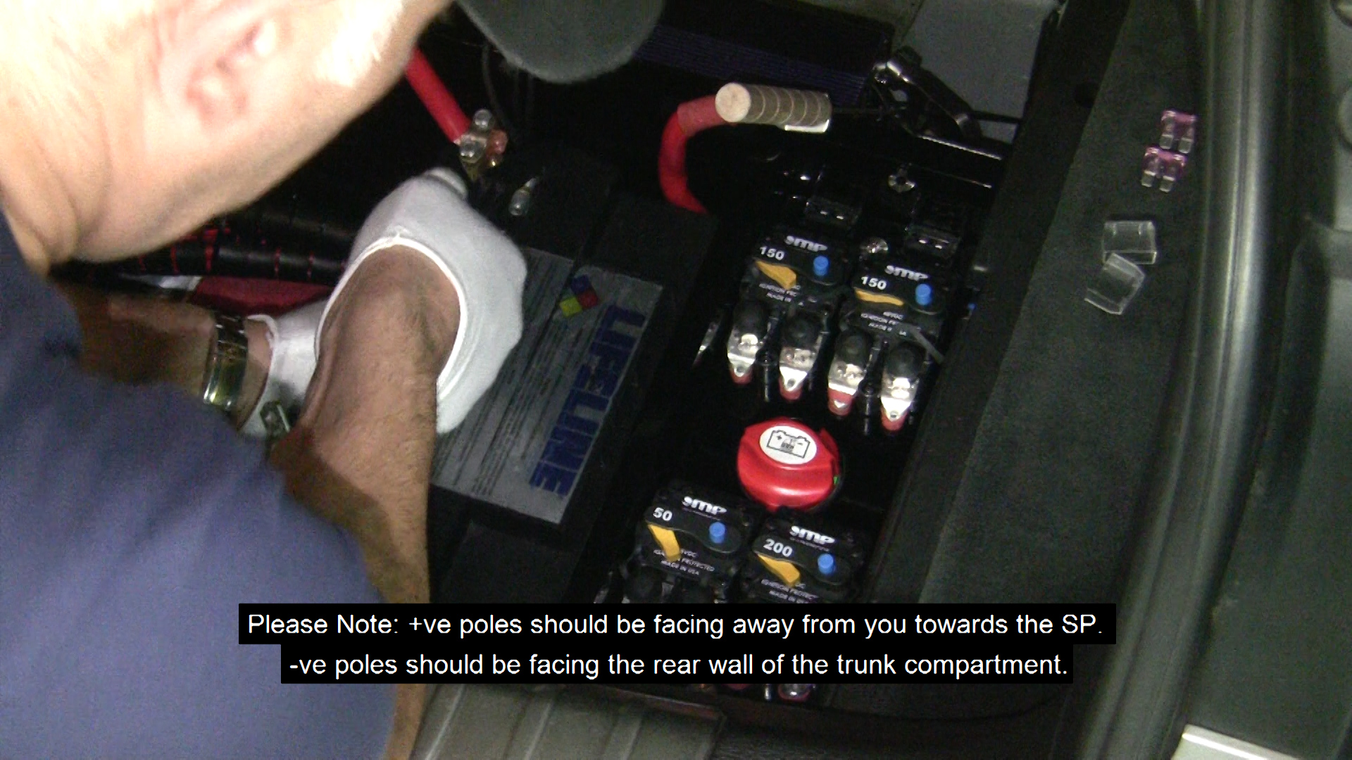
Please Note: +ve poles should be facing away from you towards the SP.
-ve poles should be facing the rear wall of the trunk compartment.
- Take the 2 ground cables (SBB/N-CHA/GND and INV/N-SBB/N) left loose near the rear wall of the trunk compartment and connect them to the -ve pole of this battery.
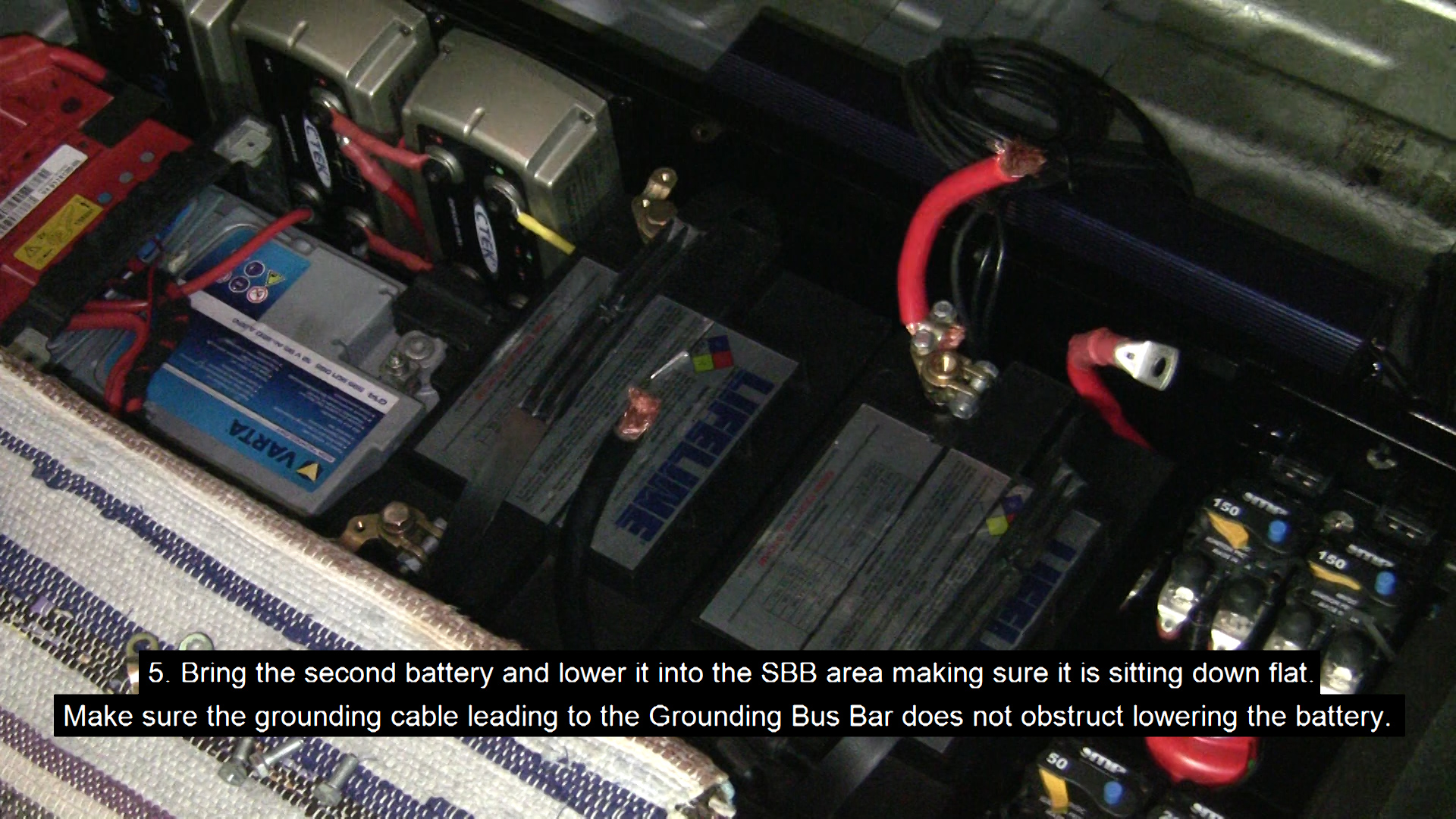
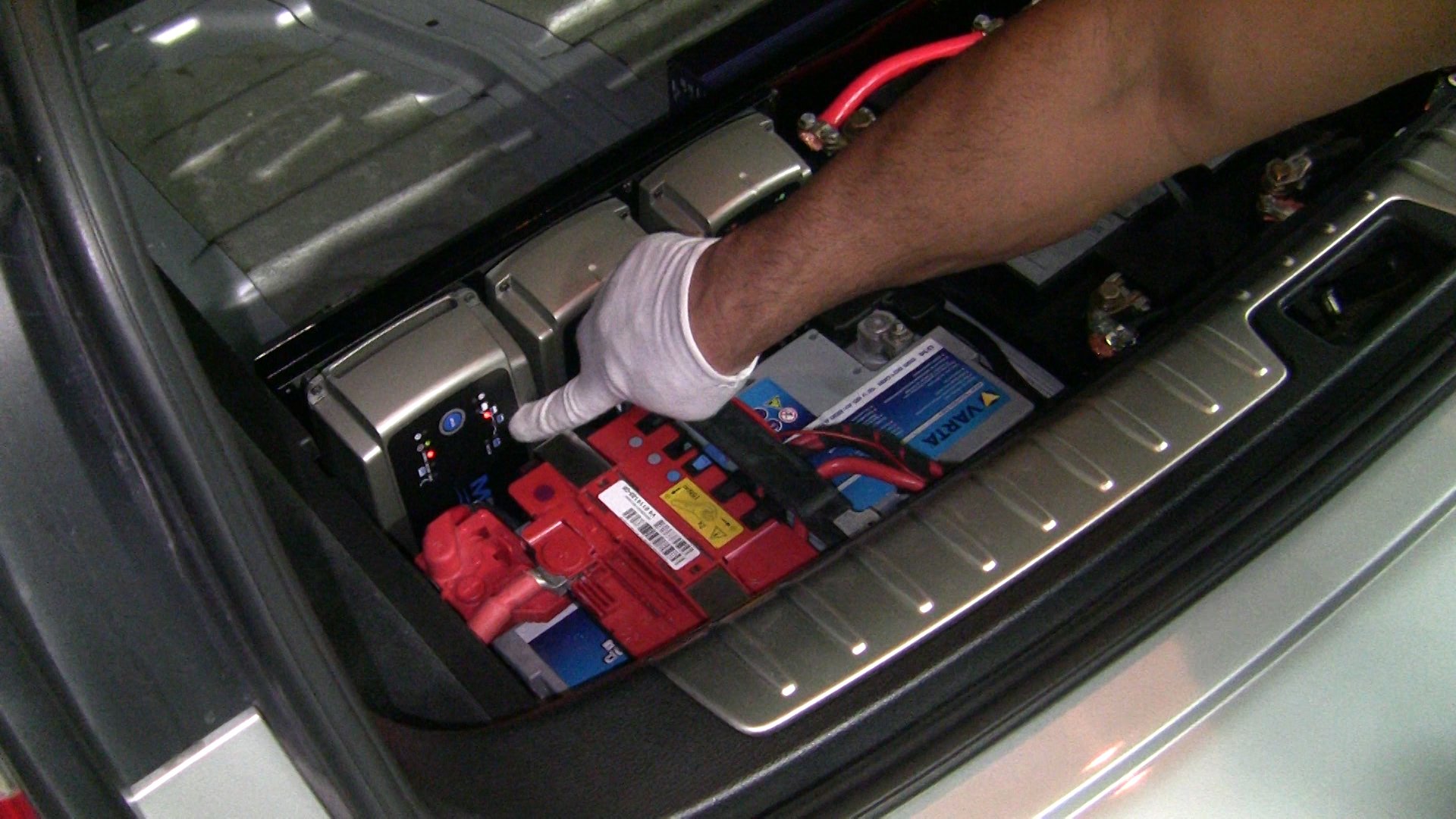
- Bring the second battery and lower it into the SBB area making sure it is sitting down flat.
Please Note: Make sure the grounding cable leading to the Grounding Bus Bar does not obstruct lowering the battery. You could try using masking tape to hold it out of the way.
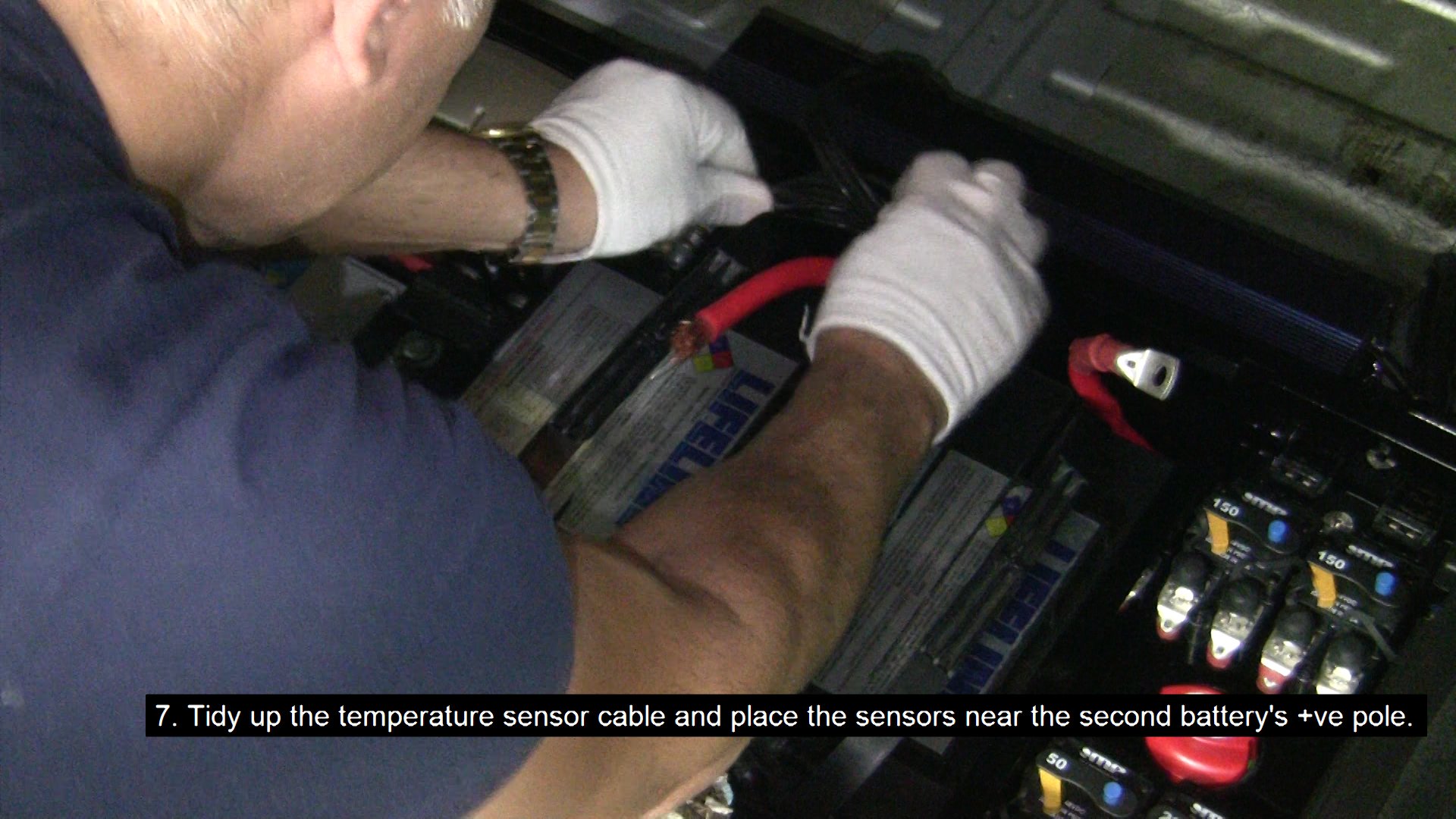
- Tidy up the temperature sensor cable and place the sensors near the second battery's +ve pole.
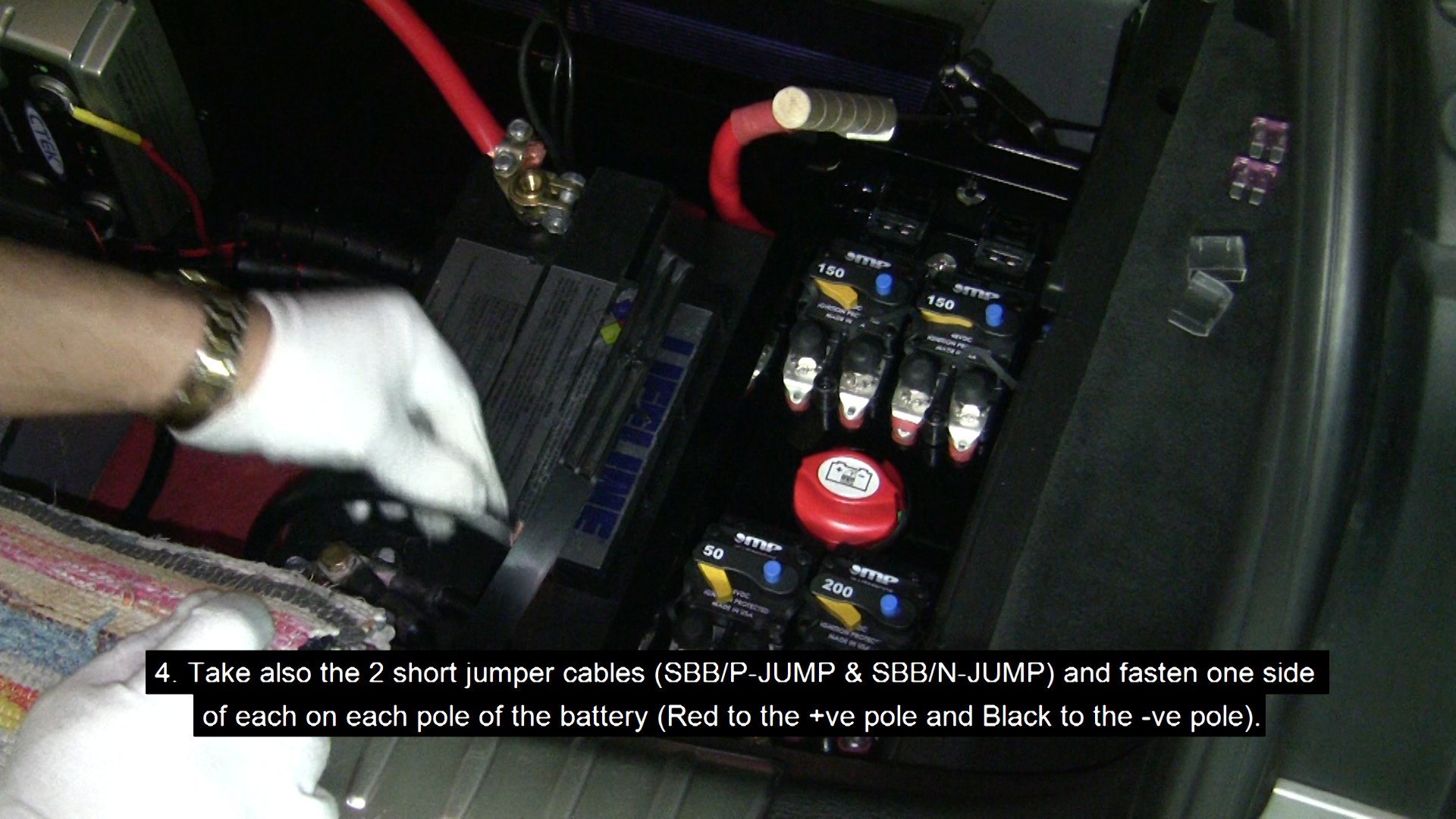
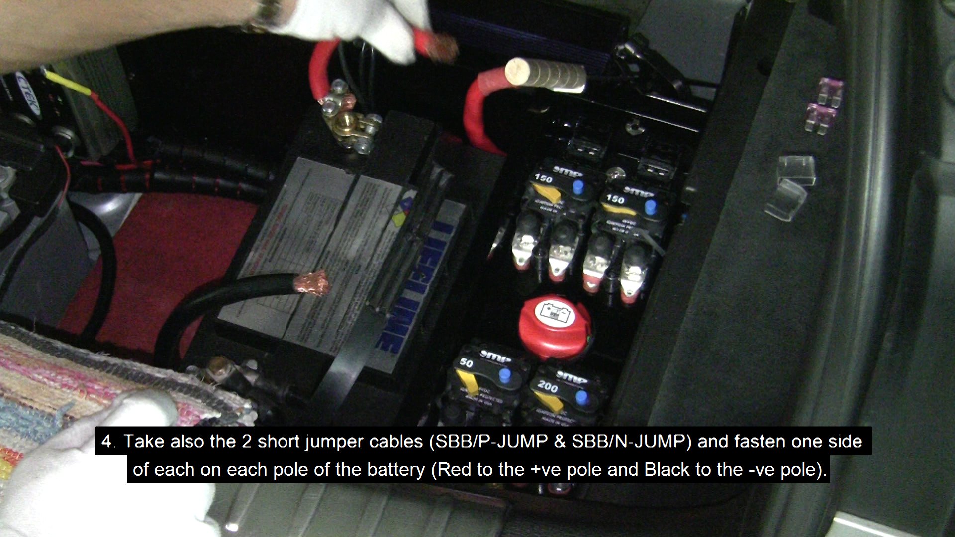
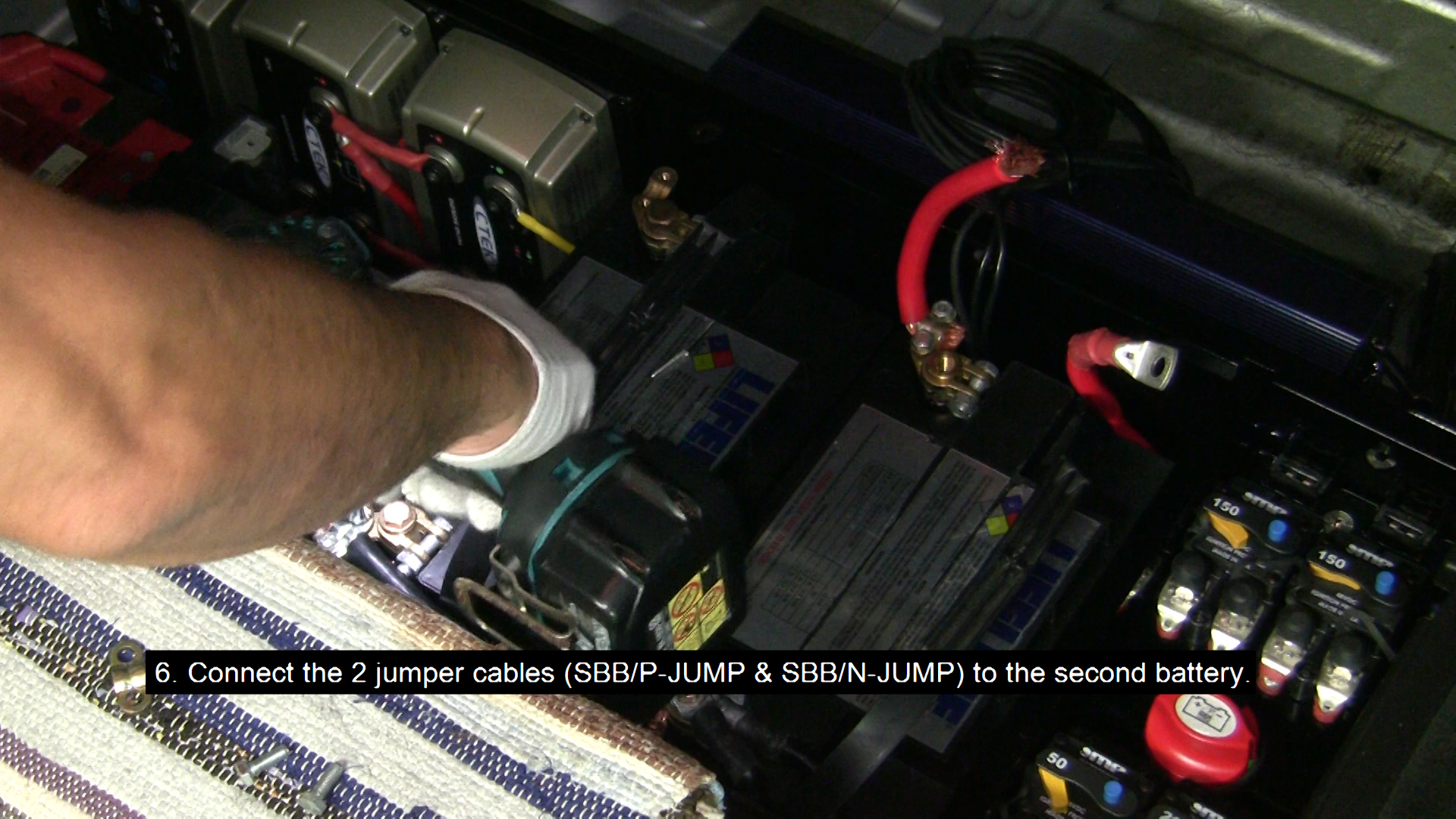
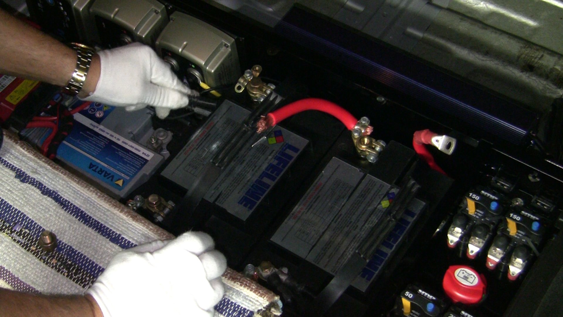
- Take the 2 short jumper cables (red - SBB/P-JUMP & black - SBB/N-JUMP) and connect the 2 batteries together (Red to the +ve poles and Black to the -ve poles).
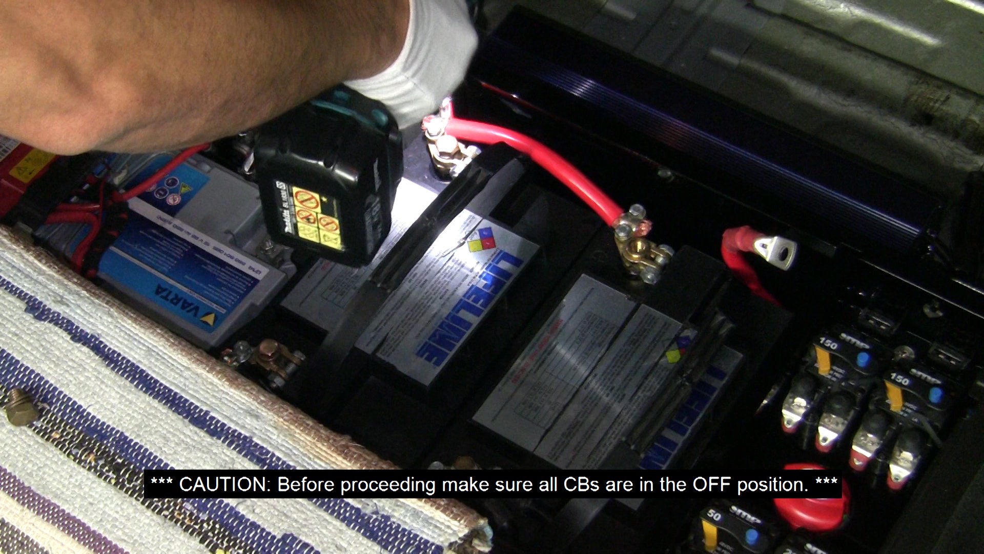
CAUTION: Before proceeding make sure all CBs are in the OFF position.
Press the blue button on each CB to disconnect it.
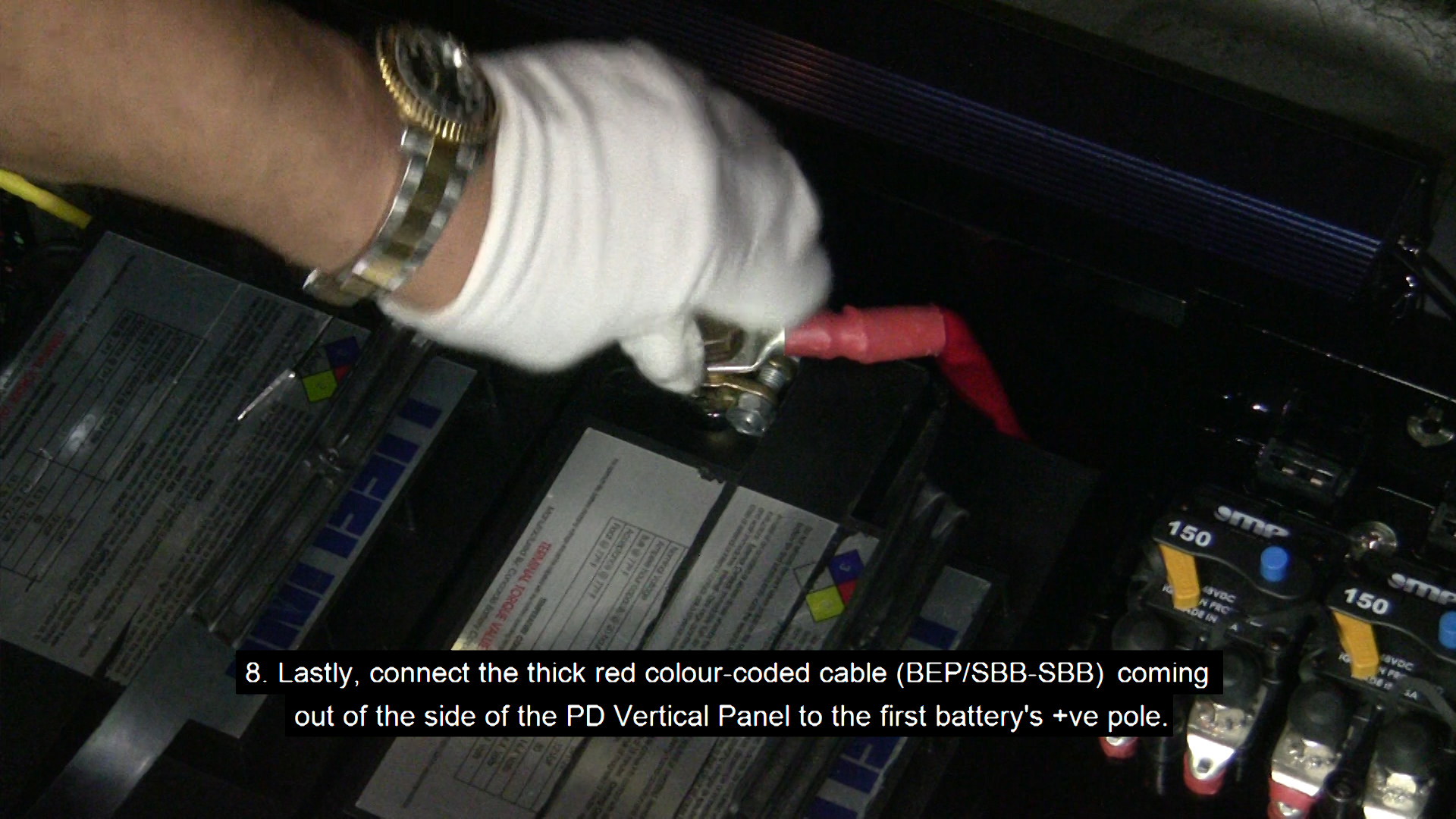
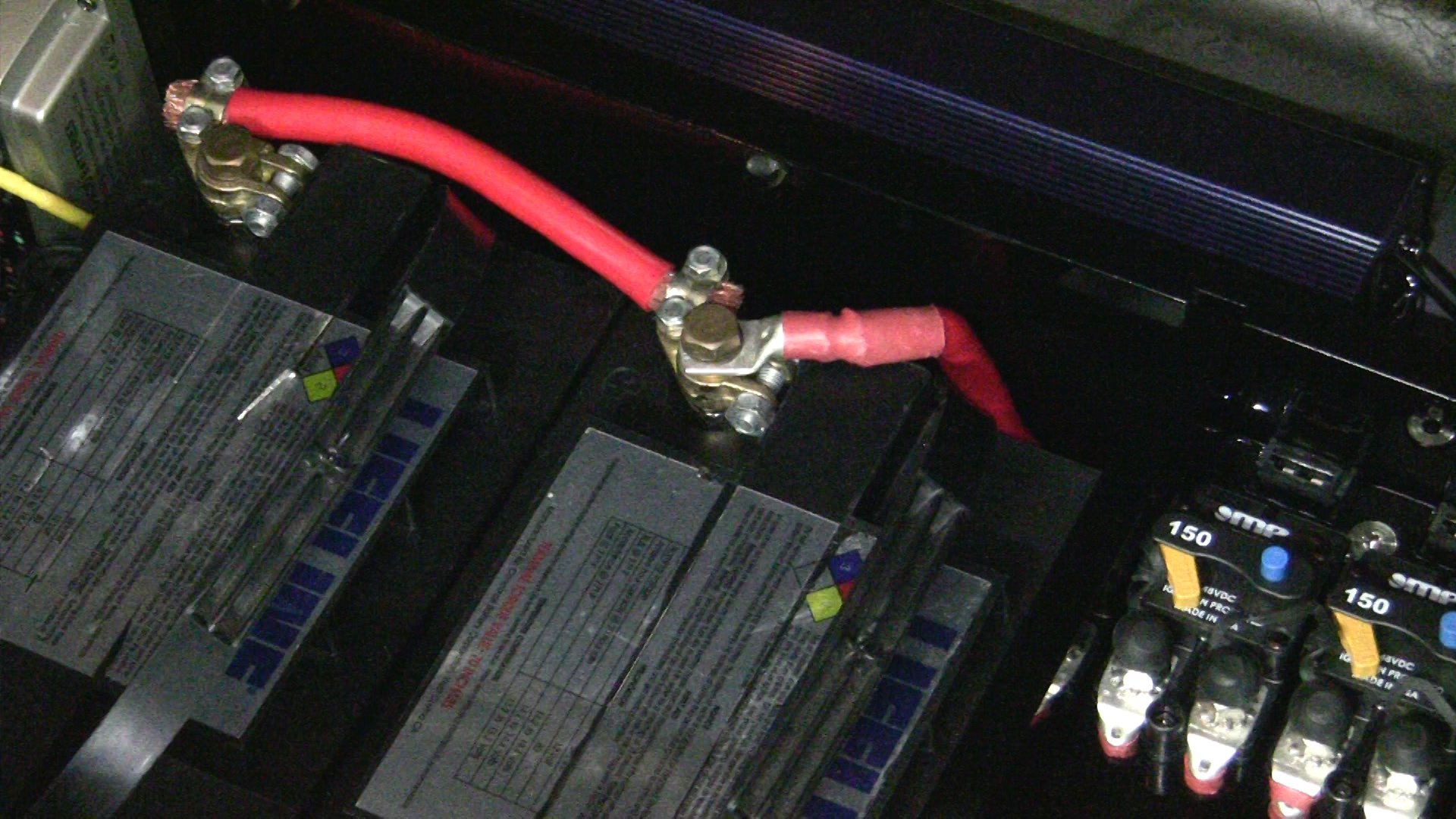
- Lastly, connect the thick red colour-coded cable (BEP/SBB-SBB) coming out of the side of the PD Vertical Panel to the first battery's +ve pole.
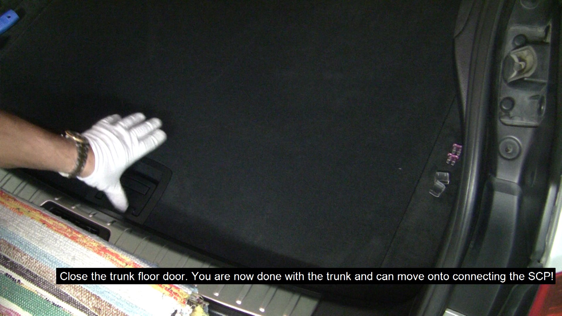
Close the trunk floor door. You are now done with the trunk
and can move onto connecting the SCP!
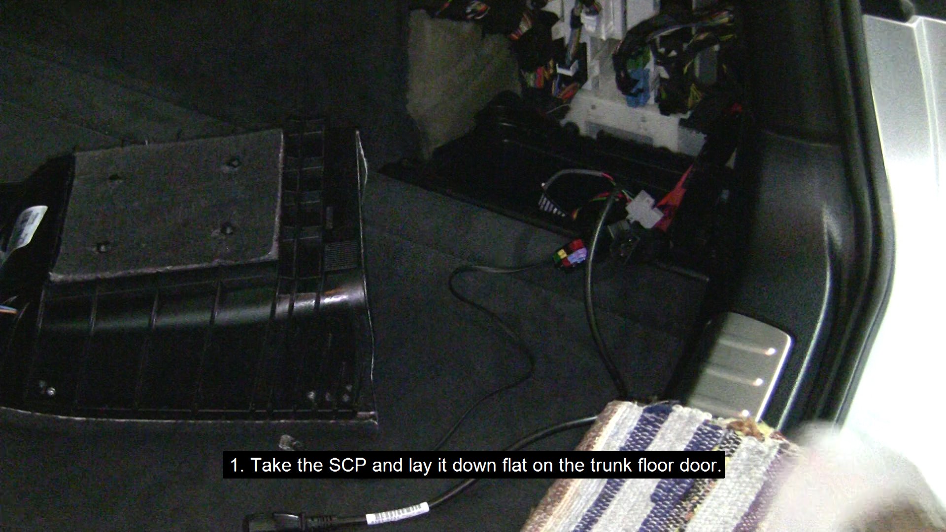
- Take the SCP and lay it down flat on the trunk floor door.
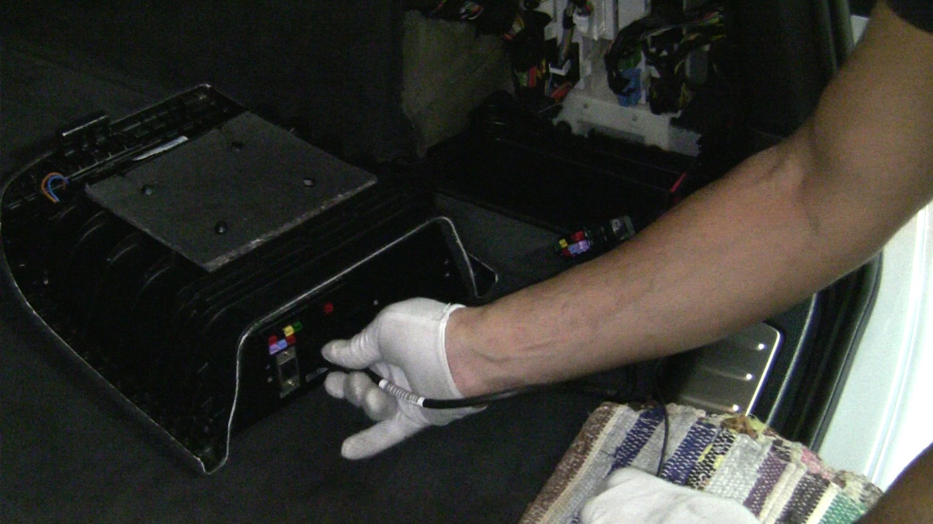
- Take each of the cables we left in the Interior-Rear-Storage Compartment Right (C) and connect them to the SCP.
CAUTION: No force is needed - may be some jiggling but no force.
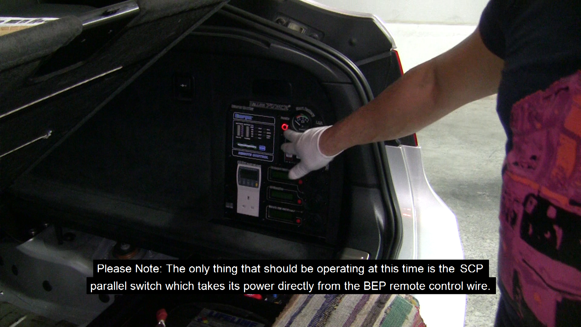
Please Note: The only thing that should be operating at this time is the SCP parallel switch which takes it power directly from the BEP remote control wire.
This is indicated by an illuminated red colored LED in the SCP parallel switch.
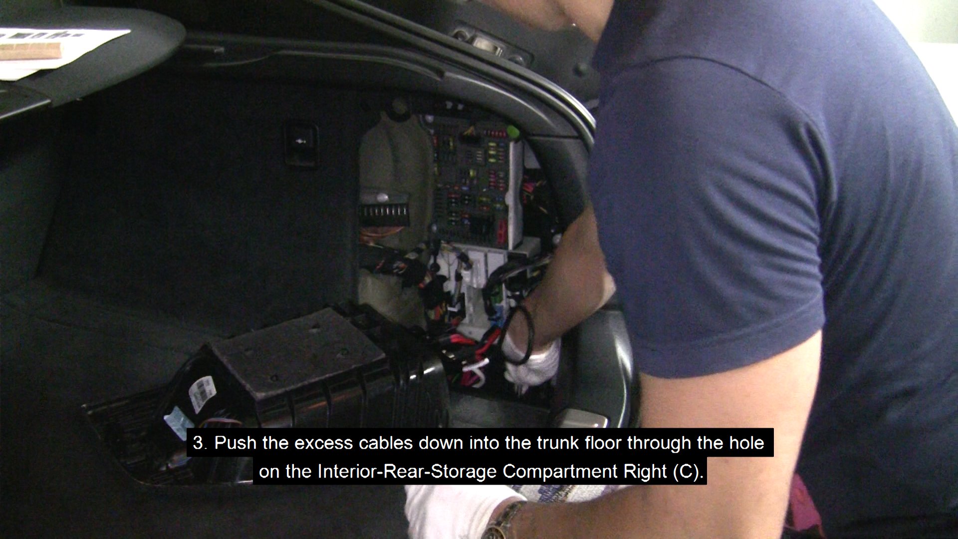
- Push the excess cables down into the trunk floor through the hole on the Interior-Rear-Storage Compartment Right (C).
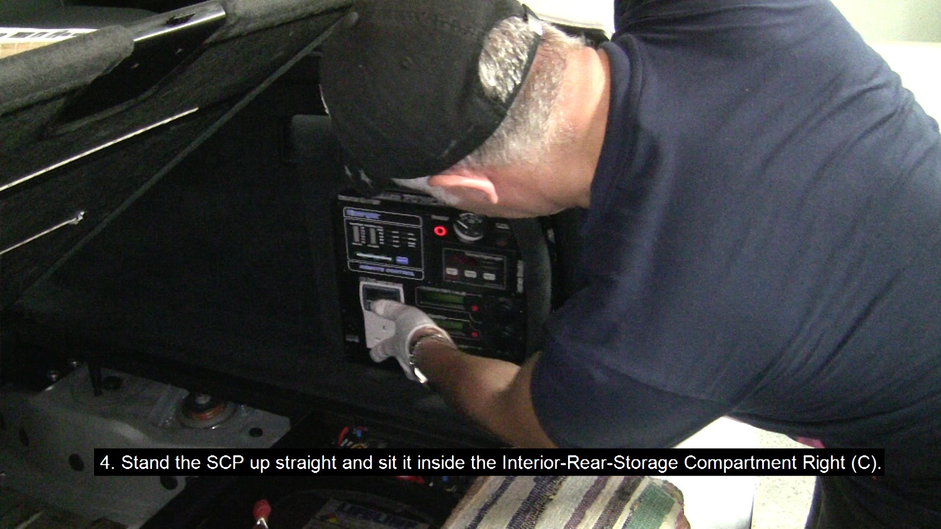
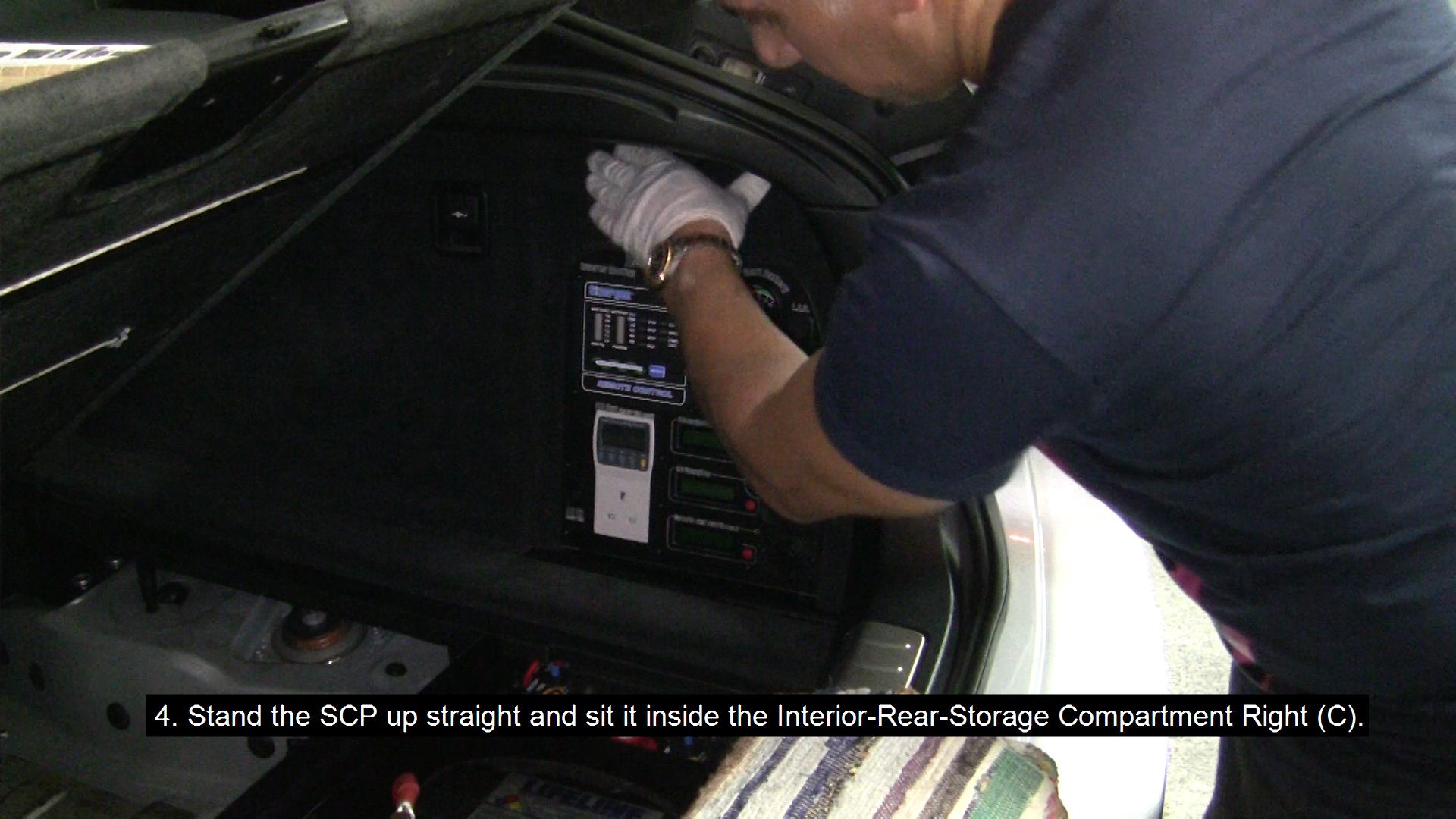
- Stand the SCP up straight and sit it inside the Interior-Rear-Storage Compartment Right (C) - again no force required (if need be, open the trunk floor and pull the cables down slightly).
- Open the trunk floor door and place each of the two 3A Fuses in their fuse boxes and then attach their covers.
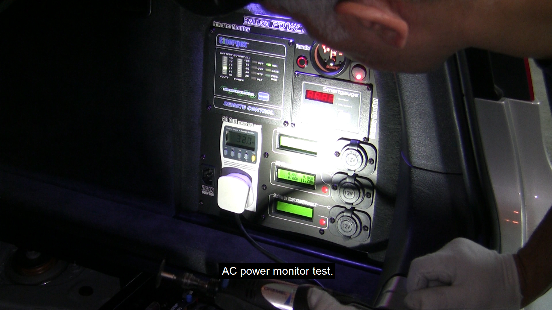
Please Note: Inserting the left fuse will activate the voltage gauge of the main car battery.
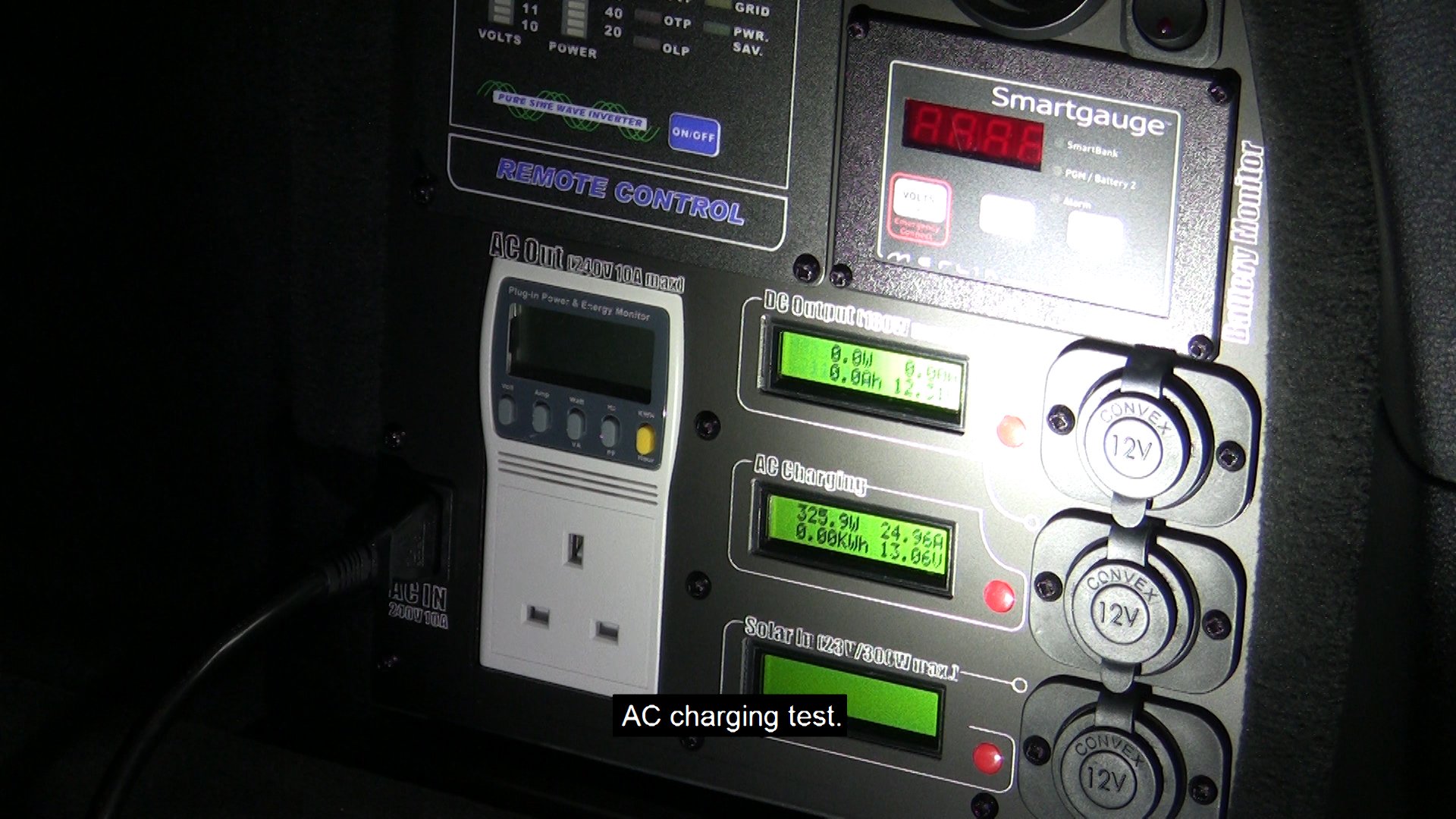
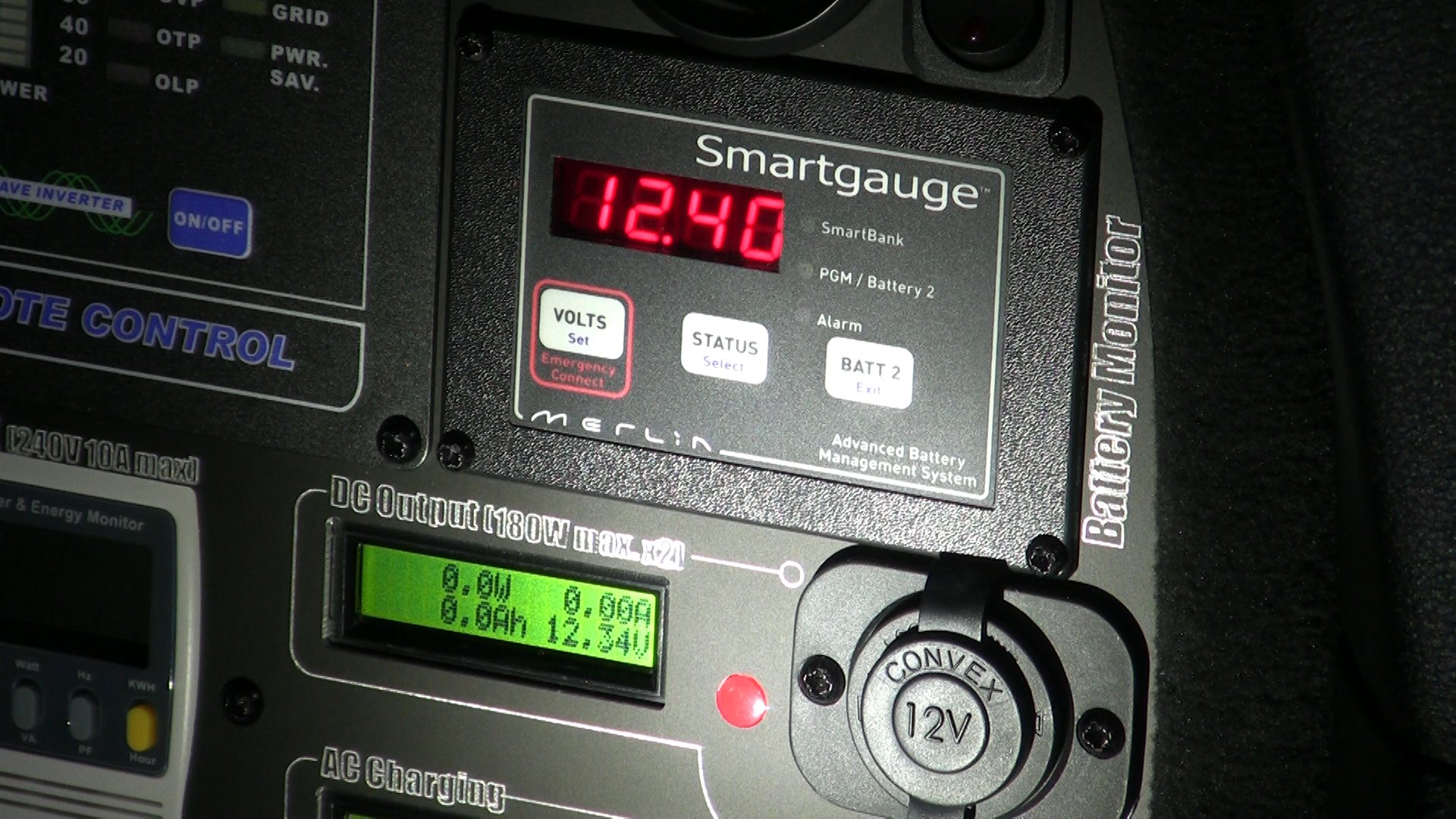
Inserting the right fuse will activate the Smartgauge and the SCP LED light which can be turned on via the light switch on the SCP.
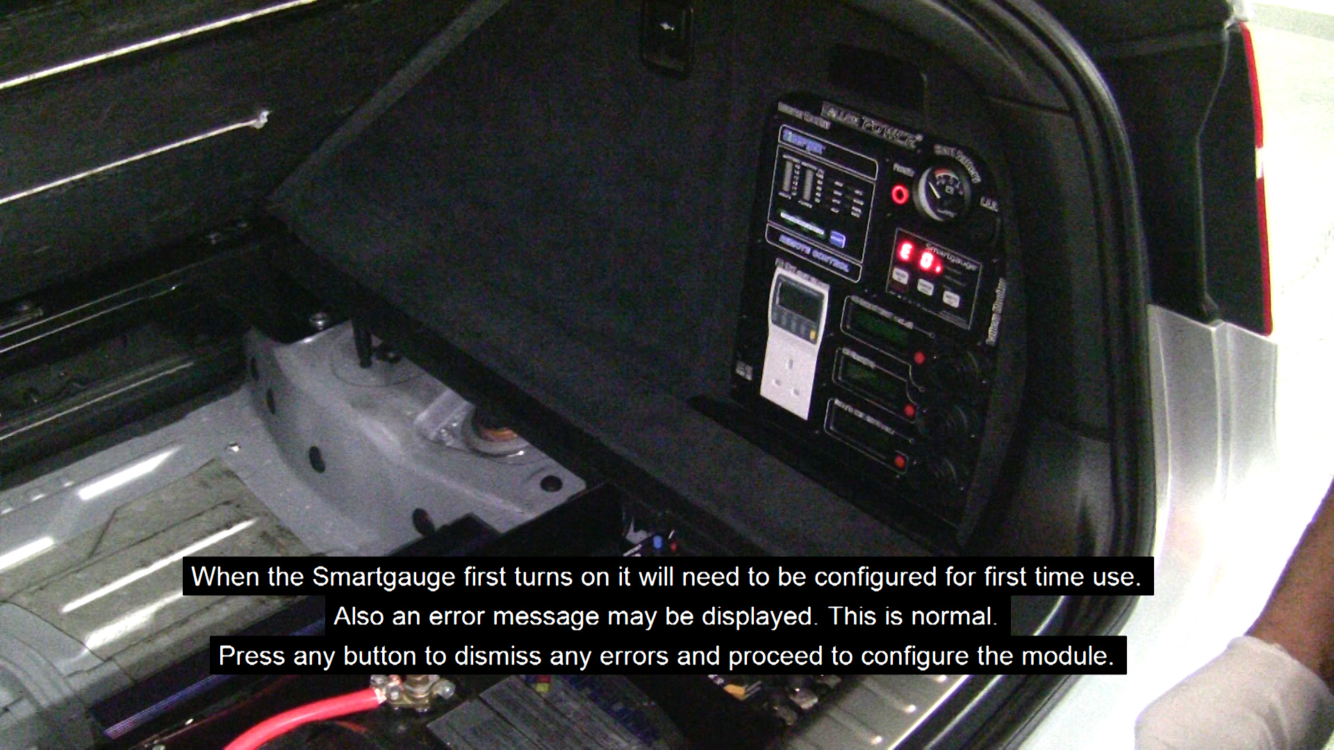
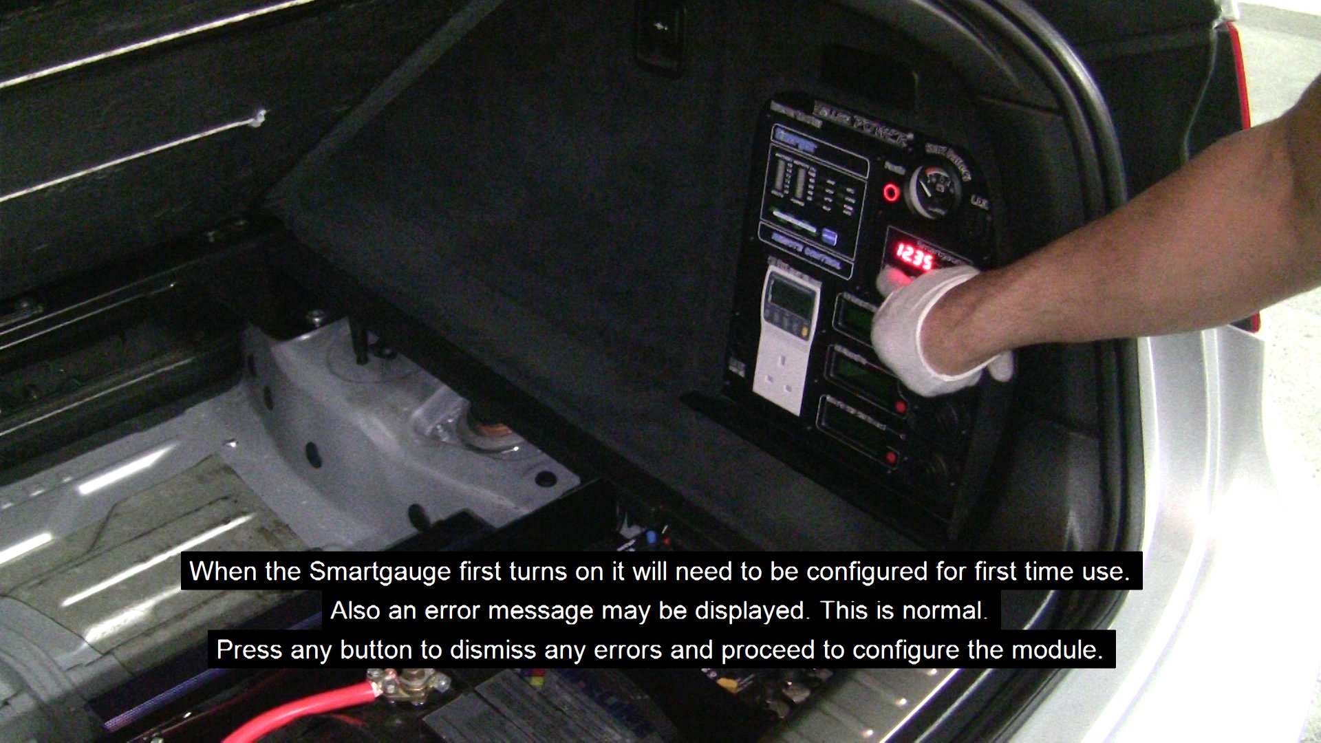
When the Smartgauge first turns on it will need to be configured for first time use specifically for your SBB.
Also an error message may be displayed. This is normal. Press any button to dismiss any errors and proceed to configure the module.
Refer to the Smartgauge user's manual on how to configure it.
You can test the motorized switch parallel function by pressing the 'Parallel' button on the SCP. It is recommended to leave the BEP701MD switch in the 'automatic OFF' position. Please refer to the BEP701MD user's manual for more.
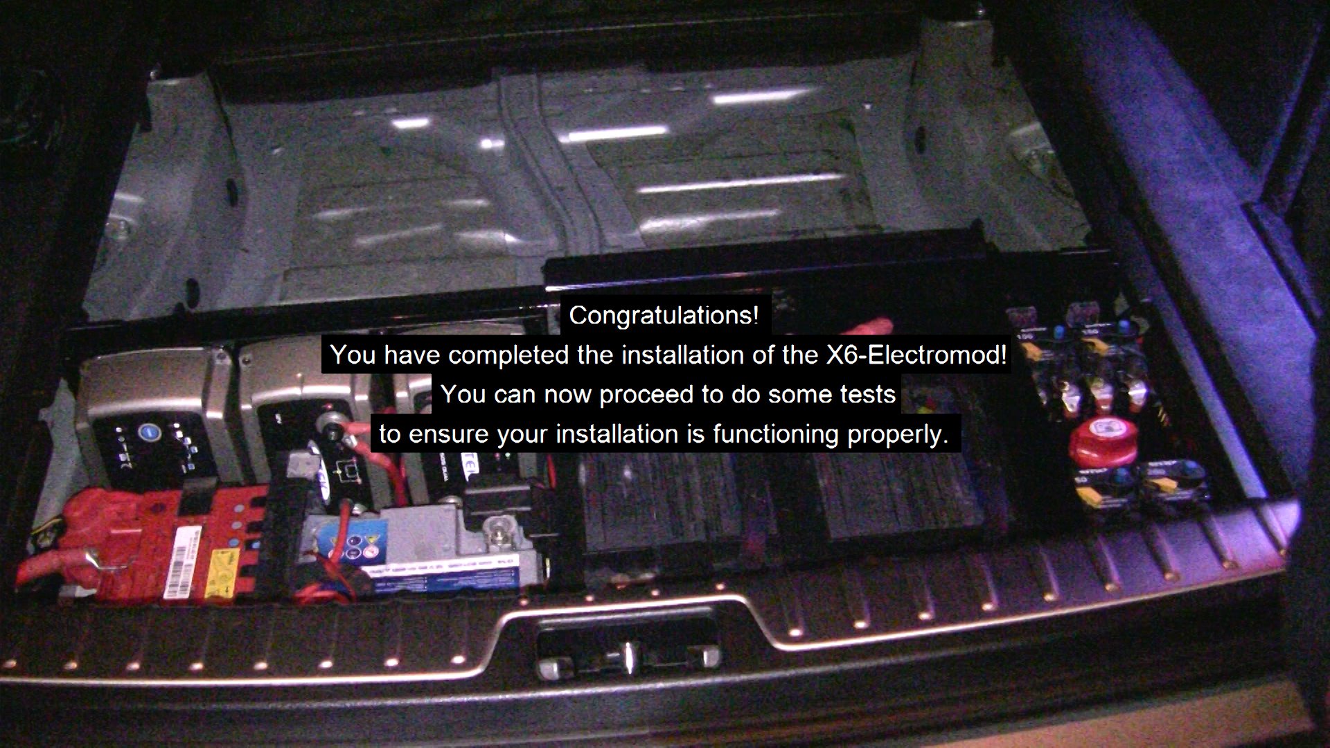
Congratulations!
You have completed the installation of the X6-Electromod!
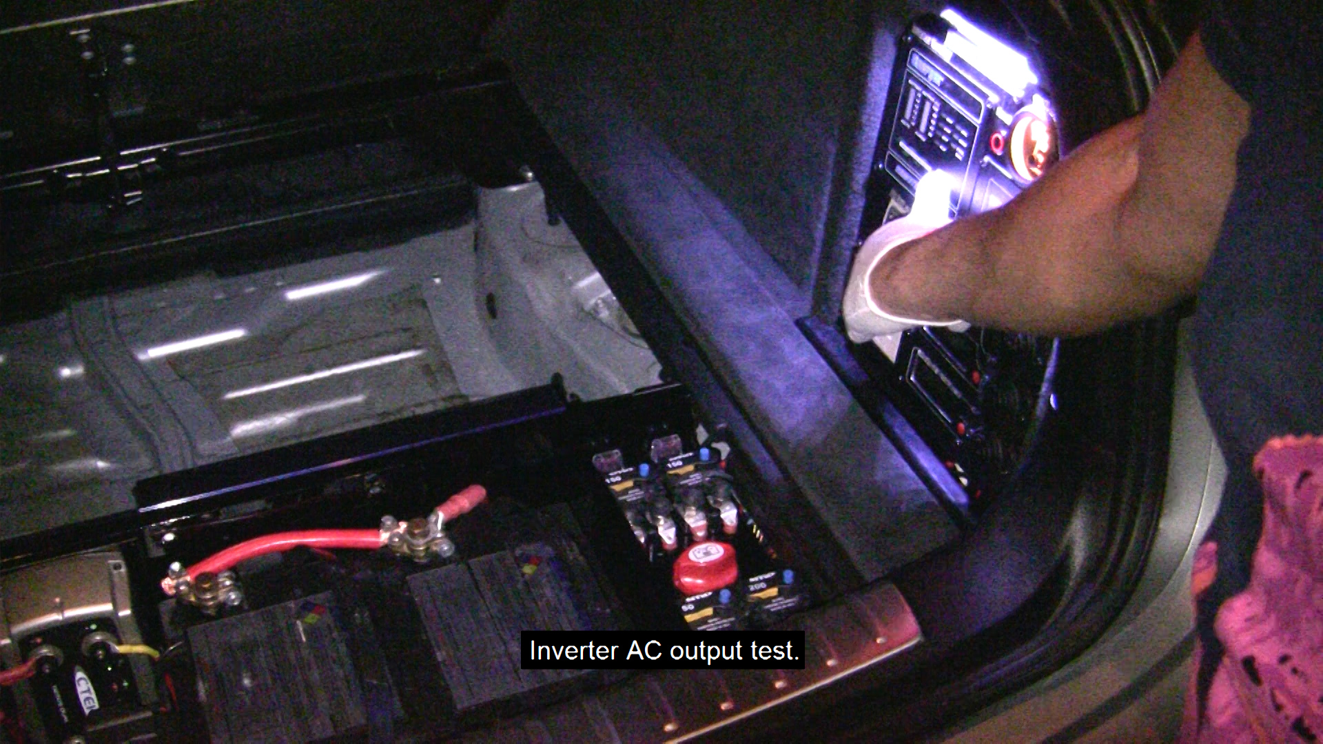
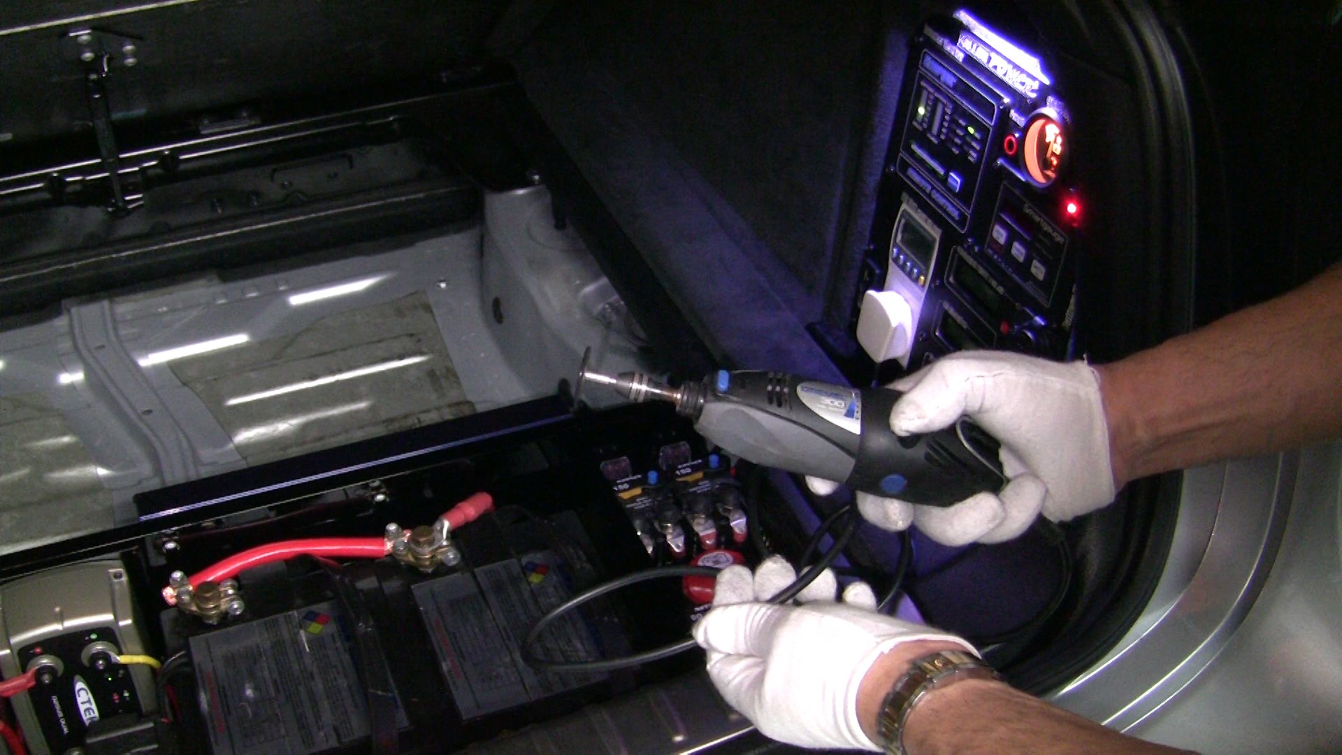
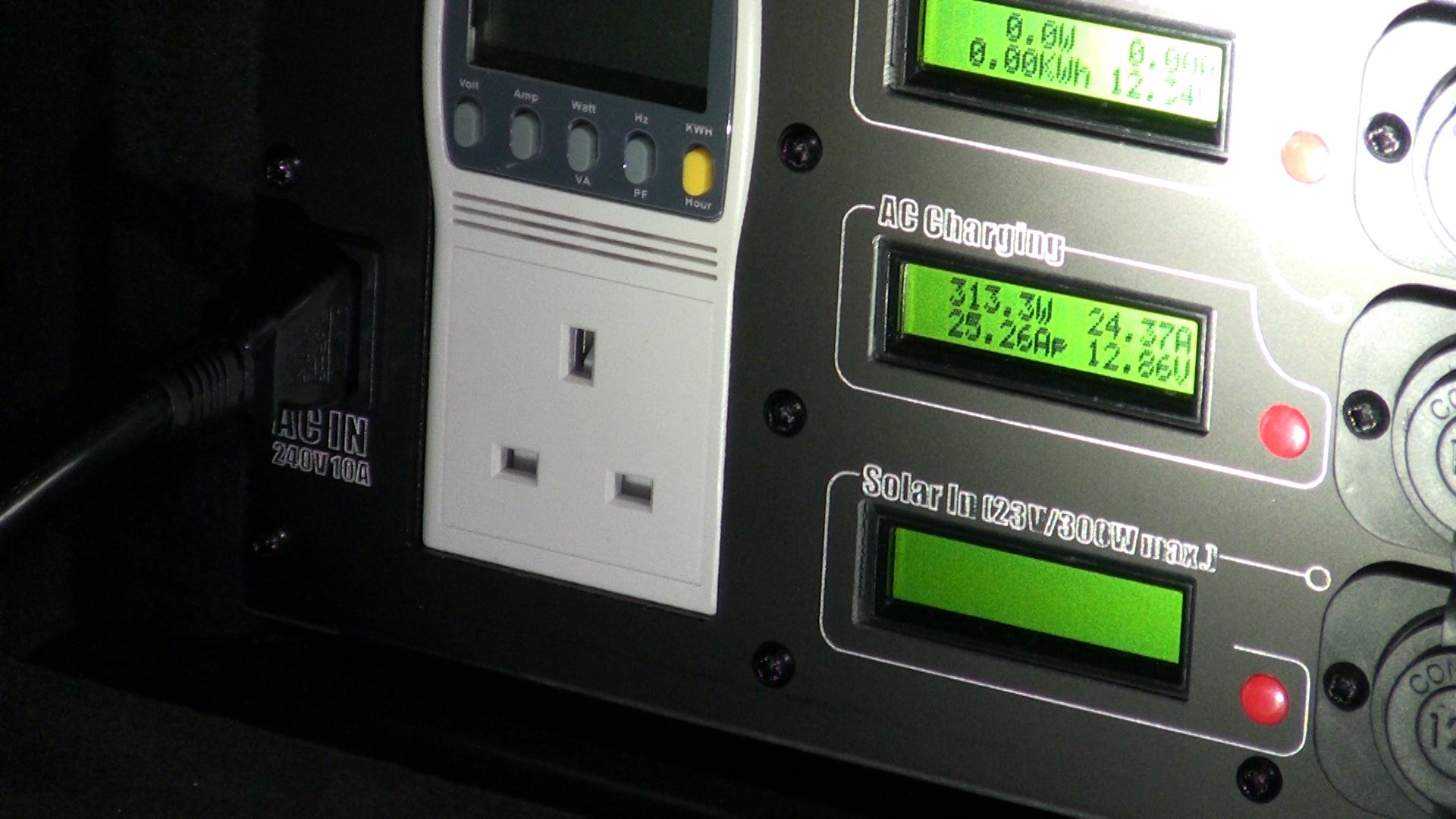
You can now proceed to do some tests to ensure your installation is functioning properly.
 2-3 Days